CloudStack Installation Documentation

_images/acslogo.png

This is the Apache CloudStack installation guide, for the Documentation home, the administrator guide or the Release-Notes please see:

Note

In this guide we first go through some design and architectural choices to build your cloud. Then we dive into a single node quick start guide to give you a feel for the installation process. The source installation steps are given in the follow-on section for people who want to build their own packages. Otherwise you can use the general installation which makes use of community maintained package repositories. The rest of the guide goes through the configuration of the data-center and the setup of the network, storage and hypervisors.

Choosing a Deployment Architecture

Choosing a Deployment Architecture

The architecture used in a deployment will vary depending on the size and purpose of the deployment. This section contains examples of deployment architecture, including a small-scale deployment useful for test and trial deployments and a fully-redundant large-scale setup for production deployments.

Small-Scale Deployment

Small-Scale Deployment

This diagram illustrates the network architecture of a small-scale CloudStack deployment.

  • A firewall provides a connection to the Internet. The firewall is configured in NAT mode. The firewall forwards HTTP requests and API calls from the Internet to the Management Server. The Management Server resides on the management network.
  • A layer-2 switch connects all physical servers and storage.
  • A single NFS server functions as both the primary and secondary storage.
  • The Management Server is connected to the management network.

Large-Scale Redundant Setup

Large-Scale Redundant Setup

This diagram illustrates the network architecture of a large-scale CloudStack deployment.

  • A layer-3 switching layer is at the core of the data center. A router redundancy protocol like VRRP should be deployed. Typically high-end core switches also include firewall modules. Separate firewall appliances may also be used if the layer-3 switch does not have integrated firewall capabilities. The firewalls are configured in NAT mode. The firewalls provide the following functions:
    • Forwards HTTP requests and API calls from the Internet to the Management Server. The Management Server resides on the management network.
    • When the cloud spans multiple zones, the firewalls should enable site-to-site VPN such that servers in different zones can directly reach each other.
  • A layer-2 access switch layer is established for each pod. Multiple switches can be stacked to increase port count. In either case, redundant pairs of layer-2 switches should be deployed.
  • The Management Server cluster (including front-end load balancers, Management Server nodes, and the MySQL database) is connected to the management network through a pair of load balancers.
  • Secondary storage servers are connected to the management network.
  • Each pod contains storage and computing servers. Each storage and computing server should have redundant NICs connected to separate layer-2 access switches.

Separate Storage Network

In the large-scale redundant setup described in the previous section, storage traffic can overload the management network. A separate storage network is optional for deployments. Storage protocols such as iSCSI are sensitive to network delays. A separate storage network ensures guest network traffic contention does not impact storage performance.

Multi-Node Management Server

The CloudStack Management Server is deployed on one or more front-end servers connected to a single MySQL database. Optionally a pair of hardware load balancers distributes requests from the web. A backup management server set may be deployed using MySQL replication at a remote site to add DR capabilities.

Multi-Node Management Server

The administrator must decide the following.

  • Whether or not load balancers will be used.
  • How many Management Servers will be deployed.
  • Whether MySQL replication will be deployed to enable disaster recovery.

Multi-Site Deployment

The CloudStack platform scales well into multiple sites through the use of zones. The following diagram shows an example of a multi-site deployment.

Example Of A Multi-Site Deployment

Data Center 1 houses the primary Management Server as well as zone 1. The MySQL database is replicated in real time to the secondary Management Server installation in Data Center 2.

Separate Storage Network

This diagram illustrates a setup with a separate storage network. Each server has four NICs, two connected to pod-level network switches and two connected to storage network switches.

There are two ways to configure the storage network:

  • Bonded NIC and redundant switches can be deployed for NFS. In NFS deployments, redundant switches and bonded NICs still result in one network (one CIDR block+ default gateway address).
  • iSCSI can take advantage of two separate storage networks (two CIDR blocks each with its own default gateway). Multipath iSCSI client can failover and load balance between separate storage networks.

NIC Bonding And Multipath I/O

This diagram illustrates the differences between NIC bonding and Multipath I/O (MPIO). NIC bonding configuration involves only one network. MPIO involves two separate networks.

Choosing a Hypervisor

CloudStack supports many popular hypervisors. Your cloud can consist entirely of hosts running a single hypervisor, or you can use multiple hypervisors. Each cluster of hosts must run the same hypervisor.

You might already have an installed base of nodes running a particular hypervisor, in which case, your choice of hypervisor has already been made. If you are starting from scratch, you need to decide what hypervisor software best suits your needs. A discussion of the relative advantages of each hypervisor is outside the scope of our documentation. However, it will help you to know which features of each hypervisor are supported by CloudStack. The following table provides this information.

Feature XenServer vSphere KVM - RHEL LXC HyperV Bare Metal
Network Throttling Yes Yes No No ? N/A
Security groups in zones that use basic networking Yes No Yes Yes ? No
iSCSI Yes Yes Yes Yes Yes N/A
FibreChannel Yes Yes Yes Yes Yes N/A
Local Disk Yes Yes Yes Yes Yes Yes
HA Yes Yes (Native) Yes ? Yes N/A
Snapshots of local disk Yes Yes Yes ? ? N/A
Local disk as data disk Yes No Yes Yes Yes N/A
Work load balancing No DRS No No ? N/A
Manual live migration of VMs from host to host Yes Yes Yes ? Yes N/A
Conserve management traffic IP address by using link local network to communicate with virtual router Yes No Yes Yes ? N/A
Hypervisor Support for Primary Storage

The following table shows storage options and parameters for different hypervisors.

Primary Storage Type XenServer vSphere KVM - RHEL LXC HyperV
Format for Disks, Templates, and Snapshots VHD VMDK QCOW2   VHD
iSCSI support CLVM VMFS Yes via Shared Mountpoint Yes via Shared Mountpoint No
Fiber Channel support Yes, Via existing SR VMFS Yes via Shared Mountpoint Yes via Shared Mountpoint No
NFS support Yes Yes Yes Yes No
Local storage support Yes Yes Yes Yes Yes
Storage over-provisioning NFS NFS and iSCSI NFS   No
SMB/CIFS No No No No Yes

XenServer uses a clustered LVM system to store VM images on iSCSI and Fiber Channel volumes and does not support over-provisioning in the hypervisor. The storage server itself, however, can support thin-provisioning. As a result the CloudStack can still support storage over-provisioning by running on thin-provisioned storage volumes.

KVM supports “Shared Mountpoint” storage. A shared mountpoint is a file system path local to each server in a given cluster. The path must be the same across all Hosts in the cluster, for example /mnt/primary1. This shared mountpoint is assumed to be a clustered filesystem such as OCFS2. In this case the CloudStack does not attempt to mount or unmount the storage as is done with NFS. The CloudStack requires that the administrator insure that the storage is available

With NFS storage, CloudStack manages the overprovisioning. In this case the global configuration parameter storage.overprovisioning.factor controls the degree of overprovisioning. This is independent of hypervisor type.

Local storage is an option for primary storage for vSphere, XenServer, and KVM. When the local disk option is enabled, a local disk storage pool is automatically created on each host. To use local storage for the System Virtual Machines (such as the Virtual Router), set system.vm.use.local.storage to true in global configuration.

CloudStack supports multiple primary storage pools in a Cluster. For example, you could provision 2 NFS servers in primary storage. Or you could provision 1 iSCSI LUN initially and then add a second iSCSI LUN when the first approaches capacity.

Best Practices

Deploying a cloud is challenging. There are many different technology choices to make, and CloudStack is flexible enough in its configuration that there are many possible ways to combine and configure the chosen technology. This section contains suggestions and requirements about cloud deployments.

These should be treated as suggestions and not absolutes. However, we do encourage anyone planning to build a cloud outside of these guidelines to seek guidance and advice on the project mailing lists.

Process Best Practices
  • A staging system that models the production environment is strongly advised. It is critical if customizations have been applied to CloudStack.
  • Allow adequate time for installation, a beta, and learning the system. Installs with basic networking can be done in hours. Installs with advanced networking usually take several days for the first attempt, with complicated installations taking longer. For a full production system, allow at least 4-8 weeks for a beta to work through all of the integration issues. You can get help from fellow users on the cloudstack-users mailing list.
Setup Best Practices
  • Each host should be configured to accept connections only from well-known entities such as the CloudStack Management Server or your network monitoring software.
  • Use multiple clusters per pod if you need to achieve a certain switch density.
  • Primary storage mountpoints or LUNs should not exceed 6 TB in size. It is better to have multiple smaller primary storage elements per cluster than one large one.
  • When exporting shares on primary storage, avoid data loss by restricting the range of IP addresses that can access the storage. See “Linux NFS on Local Disks and DAS” or “Linux NFS on iSCSI”.
  • NIC bonding is straightforward to implement and provides increased reliability.
  • 10G networks are generally recommended for storage access when larger servers that can support relatively more VMs are used.
  • Host capacity should generally be modeled in terms of RAM for the guests. Storage and CPU may be overprovisioned. RAM may not. RAM is usually the limiting factor in capacity designs.
  • (XenServer) Configure the XenServer dom0 settings to allocate more memory to dom0. This can enable XenServer to handle larger numbers of virtual machines. We recommend 2940 MB of RAM for XenServer dom0. For instructions on how to do this, see http://support.citrix.com/article/CTX126531. The article refers to XenServer 5.6, but the same information applies to XenServer 6.0.
Maintenance Best Practices
  • Monitor host disk space. Many host failures occur because the host’s root disk fills up from logs that were not rotated adequately.
  • Monitor the total number of VM instances in each cluster, and disable allocation to the cluster if the total is approaching the maximum that the hypervisor can handle. Be sure to leave a safety margin to allow for the possibility of one or more hosts failing, which would increase the VM load on the other hosts as the VMs are redeployed. Consult the documentation for your chosen hypervisor to find the maximum permitted number of VMs per host, then use CloudStack global configuration settings to set this as the default limit. Monitor the VM activity in each cluster and keep the total number of VMs below a safe level that allows for the occasional host failure. For example, if there are N hosts in the cluster, and you want to allow for one host in the cluster to be down at any given time, the total number of VM instances you can permit in the cluster is at most (N-1) * (per-host-limit). Once a cluster reaches this number of VMs, use the CloudStack UI to disable allocation to the cluster.

Warning

The lack of up-do-date hotfixes can lead to data corruption and lost VMs.

Be sure all the hotfixes provided by the hypervisor vendor are applied. Track the release of hypervisor patches through your hypervisor vendor’s support channel, and apply patches as soon as possible after they are released. CloudStack will not track or notify you of required hypervisor patches. It is essential that your hosts are completely up to date with the provided hypervisor patches. The hypervisor vendor is likely to refuse to support any system that is not up to date with patches.

Quick Installation Guide

Quick Installation Guide for CentOS 6

Overview

What exactly are we building?

Infrastructure-as-a-Service (IaaS) clouds can be a complex thing to build, and by definition they have a plethora of options, which often lead to confusion for even experienced admins who are newcomers to building cloud platforms. The goal for this runbook is to provide a straightforward set of instructions to get you up and running with CloudStack with a minimum amount of trouble.

High level overview of the process

This runbook will focus on building a CloudStack cloud using KVM on CentOS 6.5 with NFS storage on a flat layer-2 network utilizing layer-3 network isolation (aka Security Groups), and doing it all on a single piece of hardware.

KVM, or Kernel-based Virtual Machine is a virtualization technology for the Linux kernel. KVM supports native virtualization atop processors with hardware virtualization extensions.

Security Groups act as distributed firewalls that control access to a group of virtual machines.

Prerequisites

To complete this runbook you’ll need the following items:

  1. At least one computer which supports and has enabled hardware virtualization.
  2. The CentOS 6.5 x86_64 minimal install CD
  3. A /24 network with the gateway being at xxx.xxx.xxx.1, no DHCP should be on this network and none of the computers running CloudStack will have a dynamic address. Again this is done for the sake of simplicity.

Environment

Before you begin , you need to prepare the environment before you install CloudStack. We will go over the steps to prepare now.

Operating System

Using the CentOS 6.5 x86_64 minimal install ISO, you’ll need to install CentOS 6 on your hardware. The defaults will generally be acceptable for this installation.

Once this installation is complete, you’ll want to connect to your freshly installed machine via SSH as the root user. Note that you should not allow root logins in a production environment, so be sure to turn off remote logins once you have finished the installation and configuration.

Configuring the network

By default the network will not come up on your hardware and you will need to configure it to work in your environment. Since we specified that there will be no DHCP server in this environment we will be manually configuring your network interface. We will assume, for the purposes of this exercise, that eth0 is the only network interface that will be connected and used.

Connecting via the console you should login as root. Check the file /etc/sysconfig/network-scripts/ifcfg-eth0, it will look like this by default:

DEVICE="eth0"
HWADDR="52:54:00:B9:A6:C0"
NM_CONTROLLED="yes"
ONBOOT="no"

Unfortunately, this configuration will not permit you to connect to the network, and is also unsuitable for our purposes with CloudStack. We want to configure that file so that it specifies the IP address, netmask, etc., as shown in the following example:

Note

You should not use the Hardware Address (aka the MAC address) from our example for your configuration. It is network interface specific, so you should keep the address already provided in the HWADDR directive.

DEVICE=eth0
HWADDR=52:54:00:B9:A6:C0
NM_CONTROLLED=no
ONBOOT=yes
BOOTPROTO=none
IPADDR=172.16.10.2
NETMASK=255.255.255.0
GATEWAY=172.16.10.1
DNS1=8.8.8.8
DNS2=8.8.4.4

Note

IP Addressing - Throughout this document we are assuming that you will have a /24 network for your CloudStack implementation. This can be any RFC 1918 network. However, we are assuming that you will match the machine address that we are using. Thus we may use 172.16.10.2 and because you might be using the 192.168.55.0/24 network you would use 192.168.55.2

Now that we have the configuration files properly set up, we need to run a few commands to start up the network:

# chkconfig network on

# service network start
Hostname

CloudStack requires that the hostname be properly set. If you used the default options in the installation, then your hostname is currently set to localhost.localdomain. To test this we will run:

# hostname --fqdn

At this point it will likely return:

localhost

To rectify this situation - we’ll set the hostname by editing the /etc/hosts file so that it follows a similar format to this example:

127.0.0.1 localhost localhost.localdomain localhost4 localhost4.localdomain4
::1 localhost localhost.localdomain localhost6 localhost6.localdomain6
172.16.10.2 srvr1.cloud.priv

After you’ve modified that file, go ahead and restart the network using:

# service network restart

Now recheck with the hostname –fqdn command and ensure that it returns a FQDN response

SELinux

At the moment, for CloudStack to work properly SELinux must be set to permissive. We want to both configure this for future boots and modify it in the current running system.

To configure SELinux to be permissive in the running system we need to run the following command:

# setenforce 0

To ensure that it remains in that state we need to configure the file /etc/selinux/config to reflect the permissive state, as shown in this example:

# This file controls the state of SELinux on the system.
# SELINUX= can take one of these three values:
# enforcing - SELinux security policy is enforced.
# permissive - SELinux prints warnings instead of enforcing.
# disabled - No SELinux policy is loaded.
SELINUX=permissive
# SELINUXTYPE= can take one of these two values:
# targeted - Targeted processes are protected,
# mls - Multi Level Security protection.
SELINUXTYPE=targeted
NTP

NTP configuration is a necessity for keeping all of the clocks in your cloud servers in sync. However, NTP is not installed by default. So we’ll install and and configure NTP at this stage. Installation is accomplished as follows:

# yum -y install ntp

The actual default configuration is fine for our purposes, so we merely need to enable it and set it to start on boot as follows:

# chkconfig ntpd on
# service ntpd start
Configuring the CloudStack Package Repository

We need to configure the machine to use a CloudStack package repository.

Note

The Apache CloudStack official releases are source code. As such there are no ‘official’ binaries available. The full installation guide describes how to take the source release and generate RPMs and and yum repository. This guide attempts to keep things as simple as possible, and thus we are using one of the community-provided yum repositories.

To add the CloudStack repository, create /etc/yum.repos.d/cloudstack.repo and insert the following information.

[cloudstack]
name=cloudstack
baseurl=http://cloudstack.apt-get.eu/rhel/4.5/
enabled=1
gpgcheck=0
NFS

Our configuration is going to use NFS for both primary and secondary storage. We are going to go ahead and setup two NFS shares for those purposes. We’ll start out by installing nfs-utils.

# yum -y install nfs-utils

We now need to configure NFS to serve up two different shares. This is handled comparatively easily in the /etc/exports file. You should ensure that it has the following content:

/secondary *(rw,async,no_root_squash,no_subtree_check)
/primary *(rw,async,no_root_squash,no_subtree_check)

You will note that we specified two directories that don’t exist (yet) on the system. We’ll go ahead and create those directories and set permissions appropriately on them with the following commands:

# mkdir /primary
# mkdir /secondary

CentOS 6.x releases use NFSv4 by default. NFSv4 requires that domain setting matches on all clients. In our case, the domain is cloud.priv, so ensure that the domain setting in /etc/idmapd.conf is uncommented and set as follows: Domain = cloud.priv

Now you’ll need uncomment the configuration values in the file /etc/sysconfig/nfs

LOCKD_TCPPORT=32803
LOCKD_UDPPORT=32769
MOUNTD_PORT=892
RQUOTAD_PORT=875
STATD_PORT=662
STATD_OUTGOING_PORT=2020

Now we need to configure the firewall to permit incoming NFS connections. Edit the file /etc/sysconfig/iptables

-A INPUT -s 172.16.10.0/24 -m state --state NEW -p udp --dport 111 -j ACCEPT
-A INPUT -s 172.16.10.0/24 -m state --state NEW -p tcp --dport 111 -j ACCEPT
-A INPUT -s 172.16.10.0/24 -m state --state NEW -p tcp --dport 2049 -j ACCEPT
-A INPUT -s 172.16.10.0/24 -m state --state NEW -p tcp --dport 32803 -j ACCEPT
-A INPUT -s 172.16.10.0/24 -m state --state NEW -p udp --dport 32769 -j ACCEPT
-A INPUT -s 172.16.10.0/24 -m state --state NEW -p tcp --dport 892 -j ACCEPT
-A INPUT -s 172.16.10.0/24 -m state --state NEW -p udp --dport 892 -j ACCEPT
-A INPUT -s 172.16.10.0/24 -m state --state NEW -p tcp --dport 875 -j ACCEPT
-A INPUT -s 172.16.10.0/24 -m state --state NEW -p udp --dport 875 -j ACCEPT
-A INPUT -s 172.16.10.0/24 -m state --state NEW -p tcp --dport 662 -j ACCEPT
-A INPUT -s 172.16.10.0/24 -m state --state NEW -p udp --dport 662 -j ACCEPT

Now you can restart the iptables service with the following command:

# service iptables restart

We now need to configure the nfs service to start on boot and actually start it on the host by executing the following commands:

# service rpcbind start
# service nfs start
# chkconfig rpcbind on
# chkconfig nfs on

Management Server Installation

We’re going to install the CloudStack management server and surrounding tools.

Database Installation and Configuration

We’ll start with installing MySQL and configuring some options to ensure it runs well with CloudStack.

Install by running the following command:

# yum -y install mysql-server

With MySQL now installed we need to make a few configuration changes to /etc/my.cnf. Specifically we need to add the following options to the [mysqld] section:

innodb_rollback_on_timeout=1
innodb_lock_wait_timeout=600
max_connections=350
log-bin=mysql-bin
binlog-format = 'ROW'

Now that MySQL is properly configured we can start it and configure it to start on boot as follows:

# service mysqld start
# chkconfig mysqld on
Installation

We are now going to install the management server. We do that by executing the following command:

# yum -y install cloudstack-management

With the application itself installed we can now setup the database, we’ll do that with the following command and options:

# cloudstack-setup-databases cloud:password@localhost --deploy-as=root

When this process is finished, you should see a message like “CloudStack has successfully initialized the database.”

Now that the database has been created, we can take the final step in setting up the management server by issuing the following command:

# cloudstack-setup-management
System Template Setup

CloudStack uses a number of system VMs to provide functionality for accessing the console of virtual machines, providing various networking services, and managing various aspects of storage. This step will acquire those system images ready for deployment when we bootstrap your cloud.

Now we need to download the system VM template and deploy that to the share we just mounted. The management server includes a script to properly manipulate the system VMs images.

/usr/share/cloudstack-common/scripts/storage/secondary/cloud-install-sys-tmplt \
-m /secondary \
-u http://cloudstack.apt-get.eu/systemvm/4.5/systemvm64template-4.5-kvm.qcow2.bz2 \
-h kvm -F

That concludes our setup of the management server. We still need to configure CloudStack, but we will do that after we get our hypervisor set up.

KVM Setup and Installation

KVM is the hypervisor we’ll be using - we will recover the initial setup which has already been done on the hypervisor host and cover installation of the agent software, you can use the same steps to add additional KVM nodes to your CloudStack environment.

Prerequisites

We explicitly are using the management server as a compute node as well, which means that we have already performed many of the prerequisite steps when setting up the management server, but we will list them here for clarity. Those steps are:

  1. Configuring the network
  2. Hostname
  3. SELinux
  4. NTP
  5. Configuring the CloudStack Package Repository

You shouldn’t need to do that for the management server, of course, but any additional hosts will need for you to complete the above steps.

Installation

Installation of the KVM agent is trivial with just a single command, but afterwards we’ll need to configure a few things.

# yum -y install cloudstack-agent
KVM Configuration

We have two different parts of KVM to configure, libvirt, and QEMU.

QEMU Configuration

KVM configuration is relatively simple at only a single item. We need to edit the QEMU VNC configuration. This is done by editing /etc/libvirt/qemu.conf and ensuring the following line is present and uncommented.

vnc_listen=0.0.0.0
Libvirt Configuration

CloudStack uses libvirt for managing virtual machines. Therefore it is vital that libvirt is configured correctly. Libvirt is a dependency of cloud-agent and should already be installed.

  1. In order to have live migration working libvirt has to listen for unsecured TCP connections. We also need to turn off libvirts attempt to use Multicast DNS advertising. Both of these settings are in /etc/libvirt/libvirtd.conf

    Set the following paramaters:

    listen_tls = 0
    listen_tcp = 1
    tcp_port = "16059"
    auth_tcp = "none"
    mdns_adv = 0
    
  2. Turning on “listen_tcp” in libvirtd.conf is not enough, we have to change the parameters as well we also need to modify /etc/sysconfig/libvirtd:

    Uncomment the following line:

    #LIBVIRTD_ARGS="--listen"
    
  3. Restart libvirt

    # service libvirtd restart
    
KVM configuration complete
For the sake of completeness you should check if KVM is running OK on your machine:
# lsmod | grep kvm
kvm_intel              55496  0
kvm                   337772  1 kvm_intel

That concludes our installation and configuration of KVM, and we’ll now move to using the CloudStack UI for the actual configuration of our cloud.

Configuration

As we noted before we will be using security groups to provide isolation and by default that implies that we’ll be using a flat layer-2 network. It also means that the simplicity of our setup means that we can use the quick installer.

UI Access

To get access to CloudStack’s web interface, merely point your browser to http://172.16.10.2:8080/client The default username is ‘admin’, and the default password is ‘password’. You should see a splash screen that allows you to choose several options for setting up CloudStack. You should choose the Continue with Basic Setup option.

You should now see a prompt requiring you to change the password for the admin user. Please do so.

Setting up a Zone

A zone is the largest organization entity in CloudStack - and we’ll be creating one, this should be the screen that you see in front of you now. And for us there are 5 pieces of information that we need.

  1. Name - we will set this to the ever-descriptive ‘Zone1’ for our cloud.
  2. Public DNS 1 - we will set this to ‘8.8.8.8’ for our cloud.
  3. Public DNS 2 - we will set this to ‘8.8.4.4’ for our cloud.
  4. Internal DNS1 - we will also set this to ‘8.8.8.8’ for our cloud.
  5. Internal DNS2 - we will also set this to ‘8.8.4.4’ for our cloud.

Note

CloudStack distinguishes between internal and public DNS. Internal DNS is assumed to be capable of resolving internal-only hostnames, such as your NFS server’s DNS name. Public DNS is provided to the guest VMs to resolve public IP addresses. You can enter the same DNS server for both types, but if you do so, you must make sure that both internal and public IP addresses can route to the DNS server. In our specific case we will not use any names for resources internally, and we have indeed them set to look to the same external resource so as to not add a namerserver setup to our list of requirements.

Pod Configuration

Now that we’ve added a Zone, the next step that comes up is a prompt for information regading a pod. Which is looking for several items.

  1. Name - We’ll use Pod1 for our cloud.
  2. Gateway - We’ll use 172.16.10.1 as our gateway
  3. Netmask - We’ll use 255.255.255.0
  4. Start/end reserved system IPs - we will use 172.16.10.10-172.16.10.20
  5. Guest gateway - We’ll use 172.16.10.1
  6. Guest netmask - We’ll use 255.255.255.0
  7. Guest start/end IP - We’ll use 172.16.10.30-172.16.10.200
Cluster

Now that we’ve added a Zone, we need only add a few more items for configuring the cluster.

  1. Name - We’ll use Cluster1
  2. Hypervisor - Choose KVM

You should be prompted to add the first host to your cluster at this point. Only a few bits of information are needed.

  1. Hostname - we’ll use the IP address 172.16.10.2 since we didn’t set up a DNS server.
  2. Username - we’ll use ‘root’
  3. Password - enter the operating system password for the root user
Primary Storage

With your cluster now setup - you should be prompted for primary storage information. Choose NFS as the storage type and then enter the following values in the fields:

  1. Name - We’ll use ‘Primary1’
  2. Server - We’ll be using the IP address 172.16.10.2
  3. Path - Well define /primary as the path we are using
Secondary Storage

If this is a new zone, you’ll be prompted for secondary storage information - populate it as follows:

  1. NFS server - We’ll use the IP address 172.16.10.2
  2. Path - We’ll use /secondary

Now, click Launch and your cloud should begin setup - it may take several minutes depending on your internet connection speed for setup to finalize.

That’s it, you are done with installation of your Apache CloudStack cloud.

Source Installation

Building from Source

The official CloudStack release is always in source code form. You will likely be able to find “convenience binaries,” the source is the canonical release. In this section, we’ll cover acquiring the source release and building that so that you can deploy it using Maven or create Debian packages or RPMs.

Note that building and deploying directly from source is typically not the most efficient way to deploy an IaaS. However, we will cover that method as well as building RPMs or Debian packages for deploying CloudStack.

The instructions here are likely version-specific. That is, the method for building from source for the 4.5.x series is different from the 4.2.x series.

If you are working with a unreleased version of CloudStack, see the INSTALL.md file in the top-level directory of the release.

Getting the release

You can download the latest CloudStack release from the Apache CloudStack project download page.

Prior releases are available via archive.apache.org as well. See the downloads page for more information on archived releases.

You’ll notice several links under the ‘Latest release’ section. A link to a file ending in tar.bz2, as well as a PGP/GPG signature, MD5, and SHA512 file.

  • The tar.bz2 file contains the Bzip2-compressed tarball with the source code.
  • The .asc file is a detached cryptographic signature that can be used to help verify the authenticity of the release.
  • The .md5 file is an MD5 hash of the release to aid in verify the validity of the release download.
  • The .sha file is a SHA512 hash of the release to aid in verify the validity of the release download.

Verifying the downloaded release

There are a number of mechanisms to check the authenticity and validity of a downloaded release.

Getting the KEYS

To enable you to verify the GPG signature, you will need to download the KEYS file.

You next need to import those keys, which you can do by running:

$ wget http://www.apache.org/dist/cloudstack/KEYS
$ gpg --import KEYS
GPG

The CloudStack project provides a detached GPG signature of the release. To check the signature, run the following command:

$ gpg --verify apache-cloudstack-4.5.0-src.tar.bz2.asc

If the signature is valid you will see a line of output that contains ‘Good signature’.

MD5

In addition to the cryptographic signature, CloudStack has an MD5 checksum that you can use to verify the download matches the release. You can verify this hash by executing the following command:

$ gpg --print-md MD5 apache-cloudstack-4.5.0-src.tar.bz2 | diff - apache-cloudstack-4.5.0-src.tar.bz2.md5

If this successfully completes you should see no output. If there is any output from them, then there is a difference between the hash you generated locally and the hash that has been pulled from the server.

SHA512

In addition to the MD5 hash, the CloudStack project provides a SHA512 cryptographic hash to aid in assurance of the validity of the downloaded release. You can verify this hash by executing the following command:

$ gpg --print-md SHA512 apache-cloudstack-4.5.0-src.tar.bz2 | diff - apache-cloudstack-4.5.0-src.tar.bz2.sha

If this command successfully completes you should see no output. If there is any output from them, then there is a difference between the hash you generated locally and the hash that has been pulled from the server.

Prerequisites for building Apache CloudStack

There are a number of prerequisites needed to build CloudStack. This document assumes compilation on a Linux system that uses RPMs or DEBs for package management.

You will need, at a minimum, the following to compile CloudStack:

  1. Maven (version 3)
  2. Java (Java 7/OpenJDK 1.7)
  3. Apache Web Services Common Utilities (ws-commons-util)
  4. MySQL
  5. MySQLdb (provides Python database API)
  6. Tomcat 6 (not 6.0.35)
  7. genisoimage
  8. rpmbuild or dpkg-dev

Extracting source

Extracting the CloudStack release is relatively simple and can be done with a single command as follows:

$ tar -jxvf apache-cloudstack-4.5.0-src.tar.bz2

You can now move into the directory:

$ cd ./apache-cloudstack-4.5.0-src

Building DEB packages

In addition to the bootstrap dependencies, you’ll also need to install several other dependencies. Note that we recommend using Maven 3.

$ sudo apt-get update
$ sudo apt-get install python-software-properties
$ sudo apt-get update
$ sudo apt-get install ant debhelper openjdk-7-jdk tomcat6 libws-commons-util-java genisoimage python-mysqldb libcommons-codec-java libcommons-httpclient-java liblog4j1.2-java maven

While we have defined, and you have presumably already installed the bootstrap prerequisites, there are a number of build time prerequisites that need to be resolved. CloudStack uses maven for dependency resolution. You can resolve the buildtime depdencies for CloudStack by running:

$ mvn -P deps

Now that we have resolved the dependencies we can move on to building CloudStack and packaging them into DEBs by issuing the following command.

$ dpkg-buildpackage -uc -us

This command will build the following debian packages. You should have all of the following:

cloudstack-common-4.5.0.amd64.deb
cloudstack-management-4.5.0.amd64.deb
cloudstack-agent-4.5.0.amd64.deb
cloudstack-usage-4.5.0.amd64.deb
cloudstack-awsapi-4.5.0.amd64.deb
cloudstack-cli-4.5.0.amd64.deb
cloudstack-docs-4.5.0.amd64.deb
Setting up an APT repo

After you’ve created the packages, you’ll want to copy them to a system where you can serve the packages over HTTP. You’ll create a directory for the packages and then use dpkg-scanpackages to create Packages.gz, which holds information about the archive structure. Finally, you’ll add the repository to your system(s) so you can install the packages using APT.

The first step is to make sure that you have the dpkg-dev package installed. This should have been installed when you pulled in the debhelper application previously, but if you’re generating Packages.gz on a different system, be sure that it’s installed there as well.

$ sudo apt-get install dpkg-dev

The next step is to copy the DEBs to the directory where they can be served over HTTP. We’ll use /var/www/cloudstack/repo in the examples, but change the directory to whatever works for you.

$ sudo mkdir -p /var/www/cloudstack/repo/binary
$ sudo cp *.deb /var/www/cloudstack/repo/binary
$ cd /var/www/cloudstack/repo/binary
$ sudo sh -c 'dpkg-scanpackages . /dev/null | tee Packages | gzip -9 > Packages.gz'

Note

You can safely ignore the warning about a missing override file.

Now you should have all of the DEB packages and Packages.gz in the binary directory and available over HTTP. (You may want to use wget or curl to test this before moving on to the next step.)

Configuring your machines to use the APT repository

Now that we have created the repository, you need to configure your machine to make use of the APT repository. You can do this by adding a repository file under /etc/apt/sources.list.d. Use your preferred editor to create /etc/apt/sources.list.d/cloudstack.list with this line:

deb http://server.url/cloudstack/repo/binary ./

Now that you have the repository info in place, you’ll want to run another update so that APT knows where to find the CloudStack packages.

$ sudo apt-get update

You can now move on to the instructions under Install on Ubuntu.

Building RPMs from Source

As mentioned previously in “Prerequisites for building Apache CloudStack”, you will need to install several prerequisites before you can build packages for CloudStack. Here we’ll assume you’re working with a 64-bit build of CentOS or Red Hat Enterprise Linux.

# yum groupinstall "Development Tools"
# yum install java-1.7.0-openjdk-devel.x86_64 genisoimage mysql mysql-server ws-commons-util MySQL-python tomcat6 createrepo

Next, you’ll need to install build-time dependencies for CloudStack with Maven. We’re using Maven 3, so you’ll want to grab Maven 3.0.5 (Binary tar.gz) and uncompress it in your home directory (or whatever location you prefer):

$ cd ~
$ tar zxvf apache-maven-3.0.5-bin.tar.gz
$ export PATH=~/apache-maven-3.0.5/bin:$PATH

Maven also needs to know where Java is, and expects the JAVA_HOME environment variable to be set:

$ export JAVA_HOME=/usr/lib/jvm/java-1.7.0-openjdk.x86_64

Verify that Maven is installed correctly:

$ mvn --version

You probably want to ensure that your environment variables will survive a logout/reboot. Be sure to update ~/.bashrc with the PATH and JAVA_HOME variables.

Building RPMs for CloudStack is fairly simple. Assuming you already have the source downloaded and have uncompressed the tarball into a local directory, you’re going to be able to generate packages in just a few minutes.

Note

Packaging has Changed. If you’ve created packages for CloudStack previously, you should be aware that the process has changed considerably since the project has moved to using Apache Maven. Please be sure to follow the steps in this section closely.

Generating RPMS

Now that we have the prerequisites and source, you will cd to the packaging/centos63/ directory.

$ cd packaging/centos63

Generating RPMs is done using the package.sh script:

$ ./package.sh

That will run for a bit and then place the finished packages in dist/rpmbuild/RPMS/x86_64/.

You should see the following RPMs in that directory:

cloudstack-agent-4.5.0.el6.x86_64.rpm
cloudstack-awsapi-4.5.0.el6.x86_64.rpm
cloudstack-cli-4.5.0.el6.x86_64.rpm
cloudstack-common-4.5.0.el6.x86_64.rpm
cloudstack-docs-4.5.0.el6.x86_64.rpm
cloudstack-management-4.5.0.el6.x86_64.rpm
cloudstack-usage-4.5.0.el6.x86_64.rpm
Creating a yum repo

While RPMs is a useful packaging format - it’s most easily consumed from Yum repositories over a network. The next step is to create a Yum Repo with the finished packages:

$ mkdir -p ~/tmp/repo
$ cd ../..
$ cp dist/rpmbuild/RPMS/x86_64/*rpm ~/tmp/repo/
$ createrepo ~/tmp/repo

The files and directories within ~/tmp/repo can now be uploaded to a web server and serve as a yum repository.

Configuring your systems to use your new yum repository

Now that your yum repository is populated with RPMs and metadata we need to configure the machines that need to install CloudStack. Create a file named /etc/yum.repos.d/cloudstack.repo with this information:

[apache-cloudstack]
name=Apache CloudStack
baseurl=http://webserver.tld/path/to/repo
enabled=1
gpgcheck=0

Completing this step will allow you to easily install CloudStack on a number of machines across the network.

Building Non-OSS

If you need support for the VMware, NetApp, F5, NetScaler, SRX, or any other non-Open Source Software (nonoss) plugins, you’ll need to download a few components on your own and follow a slightly different procedure to build from source.

Warning

Some of the plugins supported by CloudStack cannot be distributed with CloudStack for licensing reasons. In some cases, some of the required libraries/JARs are under a proprietary license. In other cases, the required libraries may be under a license that’s not compatible with Apache’s licensing guidelines for third-party products.

  1. To build the Non-OSS plugins, you’ll need to have the requisite JARs installed under the deps directory.

    Because these modules require dependencies that can’t be distributed with CloudStack you’ll need to download them yourself. Links to the most recent dependencies are listed on the *How to build CloudStack* page on the wiki.

  2. You may also need to download vhd-util, which was removed due to licensing issues. You’ll copy vhd-util to the scripts/vm/hypervisor/xenserver/ directory.

  3. Once you have all the dependencies copied over, you’ll be able to build CloudStack with the noredist option:

$ mvn clean
$ mvn install -Dnoredist
  1. Once you’ve built CloudStack with the noredist profile, you can package it using the “Building RPMs from Source” or “Building DEB packages” instructions.

General Installation

Installation overview

Introduction

Who Should Read This

For those who have already gone through a design phase and planned a more sophisticated deployment, or those who are ready to start scaling up a trial installation. With the following procedures, you can start using the more powerful features of CloudStack, such as advanced VLAN networking, high availability, additional network elements such as load balancers and firewalls, and support for multiple hypervisors including Citrix XenServer, KVM, and VMware vSphere.

Installation Steps

For anything more than a simple trial installation, you will need guidance for a variety of configuration choices. It is strongly recommended that you read the following:

  • Choosing a Deployment Architecture
  • Choosing a Hypervisor: Supported Features
  • Network Setup
  • Storage Setup
  • Best Practices
  1. Make sure you have the required hardware ready. See Minimum System Requirements
  2. Install the Management Server (choose single-node or multi-node). See Management Server Installation
  3. Configure your cloud. See Configuring your CloudStack Installation
    1. Using CloudStack UI. See *User Interface*
    2. Add a zone. Includes the first pod, cluster, and host. See Adding a Zone
    3. Add more pods (optional). See Adding a Pod
    4. Add more clusters (optional). See Adding a Cluster
    5. Add more hosts (optional). See Adding a Host
    6. Add more primary storage (optional). See Add Primary Storage
    7. Add more secondary storage (optional). See Add Secondary Storage
  4. Try using the cloud. See Initialize and Test

Minimum System Requirements

Management Server, Database, and Storage System Requirements

The machines that will run the Management Server and MySQL database must meet the following requirements. The same machines can also be used to provide primary and secondary storage, such as via localdisk or NFS. The Management Server may be placed on a virtual machine.

  • Operating system:
    • Preferred: CentOS/RHEL 6.3+ or Ubuntu 12.04(.1)
  • 64-bit x86 CPU (more cores results in better performance)
  • 4 GB of memory
  • 250 GB of local disk (more results in better capability; 500 GB recommended)
  • At least 1 NIC
  • Statically allocated IP address
  • Fully qualified domain name as returned by the hostname command
Host/Hypervisor System Requirements

The host is where the cloud services run in the form of guest virtual machines. Each host is one machine that meets the following requirements:

  • Must support HVM (Intel-VT or AMD-V enabled).
  • 64-bit x86 CPU (more cores results in better performance)
  • Hardware virtualization support required
  • 4 GB of memory
  • 36 GB of local disk
  • At least 1 NIC
  • Latest hotfixes applied to hypervisor software
  • When you deploy CloudStack, the hypervisor host must not have any VMs already running
  • All hosts within a cluster must be homogeneous. The CPUs must be of the same type, count, and feature flags.

Hosts have additional requirements depending on the hypervisor. See the requirements listed at the top of the Installation section for your chosen hypervisor:

Warning

Be sure you fulfill the additional hypervisor requirements and installation steps provided in this Guide. Hypervisor hosts must be properly prepared to work with CloudStack. For example, the requirements for XenServer are listed under Citrix XenServer Installation.

package repository

CloudStack is only distributed from source from the official mirrors. However, members of the CloudStack community may build convenience binaries so that users can install Apache CloudStack without needing to build from source.

If you didn’t follow the steps to build your own packages from source in the sections for “Building RPMs from Source” or “Building DEB packages” you may find pre-built DEB and RPM packages for your convenience linked from the downloads page.

Note

These repositories contain both the Management Server and KVM Hypervisor packages.

Management Server Installation

Overview

This section describes installing the Management Server. There are two slightly different installation flows, depending on how many Management Server nodes will be in your cloud:

  • A single Management Server node, with MySQL on the same node.
  • Multiple Management Server nodes, with MySQL on a node separate from the Management Servers.

In either case, each machine must meet the system requirements described in Minimum System Requirements.

Warning

For the sake of security, be sure the public Internet can not access port 8096 or port 8250 on the Management Server.

The procedure for installing the Management Server is:

  1. Prepare the Operating System
  2. (XenServer only) Download and install vhd-util.
  3. Install the First Management Server
  4. Install and Configure the MySQL database
  5. Prepare NFS Shares
  6. Prepare and Start Additional Management Servers (optional)
  7. Prepare the System VM Template

Prepare the Operating System

The OS must be prepared to host the Management Server using the following steps. These steps must be performed on each Management Server node.

  1. Log in to your OS as root.

  2. Check for a fully qualified hostname.

    hostname --fqdn
    

    This should return a fully qualified hostname such as “management1.lab.example.org”. If it does not, edit /etc/hosts so that it does.

  3. Make sure that the machine can reach the Internet.

    ping www.cloudstack.org
    
  4. Turn on NTP for time synchronization.

    Note

    NTP is required to synchronize the clocks of the servers in your cloud.

    Install NTP.

    yum install ntp
    
    sudo apt-get install openntpd
    
  5. Repeat all of these steps on every host where the Management Server will be installed.

Install the Management Server on the First Host

The first step in installation, whether you are installing the Management Server on one host or many, is to install the software on a single node.

Note

If you are planning to install the Management Server on multiple nodes for high availability, do not proceed to the additional nodes yet. That step will come later.

The CloudStack Management server can be installed using either RPM or DEB packages. These packages will depend on everything you need to run the Management server.

Configure package repository

CloudStack is only distributed from source from the official mirrors. However, members of the CloudStack community may build convenience binaries so that users can install Apache CloudStack without needing to build from source.

If you didn’t follow the steps to build your own packages from source in the sections for “Building RPMs from Source” or “Building DEB packages” you may find pre-built DEB and RPM packages for your convenience linked from the downloads page.

Note

These repositories contain both the Management Server and KVM Hypervisor packages.

RPM package repository

There is a RPM package repository for CloudStack so you can easily install on RHEL based platforms.

If you’re using an RPM-based system, you’ll want to add the Yum repository so that you can install CloudStack with Yum.

Yum repository information is found under /etc/yum.repos.d. You’ll see several .repo files in this directory, each one denoting a specific repository.

To add the CloudStack repository, create /etc/yum.repos.d/cloudstack.repo and insert the following information.

[cloudstack]
name=cloudstack
baseurl=http://cloudstack.apt-get.eu/rhel/4.5/
enabled=1
gpgcheck=0

Now you should be able to install CloudStack using Yum.

DEB package repository

You can add a DEB package repository to your apt sources with the following commands. Please note that only packages for Ubuntu 12.04 LTS (precise) are being built at this time.

Use your preferred editor and open (or create) /etc/apt/sources.list.d/cloudstack.list. Add the community provided repository to the file:

deb http://cloudstack.apt-get.eu/ubuntu precise 4.5

We now have to add the public key to the trusted keys.

sudo wget -O - http://cloudstack.apt-get.eu/release.asc|apt-key add -

Now update your local apt cache.

sudo apt-get update

Your DEB package repository should now be configured and ready for use.

Install on CentOS/RHEL
yum install cloudstack-management
Install on Ubuntu
sudo apt-get install cloudstack-management

Downloading vhd-util

This procedure is required only for installations where XenServer is installed on the hypervisor hosts.

Before setting up the Management Server, download vhd-util from http://download.cloud.com.s3.amazonaws.com/tools/vhd-util. and copy it into /usr/share/cloudstack-common/scripts/vm/hypervisor/xenserver of the Management Server.

Install the database server

The CloudStack management server uses a MySQL database server to store its data. When you are installing the management server on a single node, you can install the MySQL server locally. For an installation that has multiple management server nodes, we assume the MySQL database also runs on a separate node.

CloudStack has been tested with MySQL 5.1 and 5.5. These versions are included in RHEL/CentOS and Ubuntu.

Install the Database on the Management Server Node

This section describes how to install MySQL on the same machine with the Management Server. This technique is intended for a simple deployment that has a single Management Server node. If you have a multi-node Management Server deployment, you will typically use a separate node for MySQL. See Install the Database on a Separate Node.

  1. Install MySQL from the package repository of your distribution:

    yum install mysql-server
    
    sudo apt-get install mysql-server
    
  2. Open the MySQL configuration file. The configuration file is /etc/my.cnf or /etc/mysql/my.cnf, depending on your OS.

    Insert the following lines in the [mysqld] section.

    You can put these lines below the datadir line. The max_connections parameter should be set to 350 multiplied by the number of Management Servers you are deploying. This example assumes one Management Server.

    innodb_rollback_on_timeout=1
    innodb_lock_wait_timeout=600
    max_connections=350
    log-bin=mysql-bin
    binlog-format = 'ROW'
    

    Note

    You can also create a file /etc/mysql/conf.d/cloudstack.cnf and add these directives there. Don’t forget to add [mysqld] on the first line of the file.

  3. Start or restart MySQL to put the new configuration into effect.

    On RHEL/CentOS, MySQL doesn’t automatically start after installation. Start it manually.

    service mysqld start
    

    On Ubuntu, restart MySQL.

    sudo service mysql restart
    
  4. (CentOS and RHEL only; not required on Ubuntu)

    Warning

    On RHEL and CentOS, MySQL does not set a root password by default. It is very strongly recommended that you set a root password as a security precaution.

    Run the following command to secure your installation. You can answer “Y” to all questions.

    mysql_secure_installation
    
  5. CloudStack can be blocked by security mechanisms, such as SELinux. Disable SELinux to ensure + that the Agent has all the required permissions.

    Configure SELinux (RHEL and CentOS):

    1. Check whether SELinux is installed on your machine. If not, you can skip this section.

      In RHEL or CentOS, SELinux is installed and enabled by default. You can verify this with:

      rpm -qa | grep selinux
      
    2. Set the SELINUX variable in /etc/selinux/config to “permissive”. This ensures that the permissive setting will be maintained after a system reboot.

      In RHEL or CentOS:

      vi /etc/selinux/config
      

      Change the following line

      SELINUX=enforcing
      

      to this:

      SELINUX=permissive
      
    3. Set SELinux to permissive starting immediately, without requiring a system reboot.

      setenforce permissive
      
  6. Set up the database. The following command creates the “cloud” user on the database.

    cloudstack-setup-databases cloud:<dbpassword>@localhost \
    --deploy-as=root:<password> \
    -e <encryption_type> \
    -m <management_server_key> \
    -k <database_key> \
    -i <management_server_ip>
    
    • In dbpassword, specify the password to be assigned to the “cloud” user. You can choose to provide no password although that is not recommended.
    • In deploy-as, specify the username and password of the user deploying the database. In the following command, it is assumed the root user is deploying the database and creating the “cloud” user.
    • (Optional) For encryption_type, use file or web to indicate the technique used to pass in the database encryption password. Default: file. See About Password and Key Encryption.
    • (Optional) For management_server_key, substitute the default key that is used to encrypt confidential parameters in the CloudStack properties file. Default: password. It is highly recommended that you replace this with a more secure value. See About Password and Key Encryption.
    • (Optional) For database_key, substitute the default key that is used to encrypt confidential parameters in the CloudStack database. Default: password. It is highly recommended that you replace this with a more secure value. See About Password and Key Encryption.
    • (Optional) For management_server_ip, you may explicitly specify cluster management server node IP. If not specified, the local IP address will be used.

    When this script is finished, you should see a message like “Successfully initialized the database.”

    Note

    If the script is unable to connect to the MySQL database, check the “localhost” loopback address in /etc/hosts. It should be pointing to the IPv4 loopback address “127.0.0.1” and not the IPv6 loopback address ::1. Alternatively, reconfigure MySQL to bind to the IPv6 loopback interface.

  7. If you are running the KVM hypervisor on the same machine with the Management Server, edit /etc/sudoers and add the following line:

    Defaults:cloud !requiretty
    
  8. Now that the database is set up, you can finish configuring the OS for the Management Server. This command will set up iptables, sudoers, and start the Management Server.

    cloudstack-setup-management
    

    You should get the output message “CloudStack Management Server setup is done.”

Install the Database on a Separate Node

This section describes how to install MySQL on a standalone machine, separate from the Management Server. This technique is intended for a deployment that includes several Management Server nodes. If you have a single-node Management Server deployment, you will typically use the same node for MySQL. See “Install the Database on the Management Server Node”.

Note

The management server doesn’t require a specific distribution for the MySQL node. You can use a distribution or Operating System of your choice. Using the same distribution as the management server is recommended, but not required. See “Management Server, Database, and Storage System Requirements”.

  1. Install MySQL from the package repository from your distribution:

    yum install mysql-server
    
    sudo apt-get install mysql-server
    
  2. Edit the MySQL configuration (/etc/my.cnf or /etc/mysql/my.cnf, depending on your OS) and insert the following lines in the [mysqld] section. You can put these lines below the datadir line. The max_connections parameter should be set to 350 multiplied by the number of Management Servers you are deploying. This example assumes two Management Servers.

    Note

    On Ubuntu, you can also create /etc/mysql/conf.d/cloudstack.cnf file and add these directives there. Don’t forget to add [mysqld] on the first line of the file.

    innodb_rollback_on_timeout=1
    innodb_lock_wait_timeout=600
    max_connections=700
    log-bin=mysql-bin
    binlog-format = 'ROW'
    bind-address = 0.0.0.0
    
  3. Start or restart MySQL to put the new configuration into effect.

    On RHEL/CentOS, MySQL doesn’t automatically start after installation. Start it manually.

    service mysqld start
    

    On Ubuntu, restart MySQL.

    sudo service mysql restart
    
  4. (CentOS and RHEL only; not required on Ubuntu)

    Warning

    On RHEL and CentOS, MySQL does not set a root password by default. It is very strongly recommended that you set a root password as a security precaution. Run the following command to secure your installation. You can answer “Y” to all questions except “Disallow root login remotely?”. Remote root login is required to set up the databases.

    mysql_secure_installation
    
  5. If a firewall is present on the system, open TCP port 3306 so external MySQL connections can be established.

    On Ubuntu, UFW is the default firewall. Open the port with this command:

    ufw allow mysql
    

    On RHEL/CentOS:

    1. Edit the /etc/sysconfig/iptables file and add the following line at the beginning of the INPUT chain.

      -A INPUT -p tcp --dport 3306 -j ACCEPT
      
    2. Now reload the iptables rules.

      service iptables restart
      
  6. Return to the root shell on your first Management Server.

  7. Set up the database. The following command creates the cloud user on the database.

    • In dbpassword, specify the password to be assigned to the cloud user. You can choose to provide no password.
    • In deploy-as, specify the username and password of the user deploying the database. In the following command, it is assumed the root user is deploying the database and creating the cloud user.
    • (Optional) For encryption_type, use file or web to indicate the technique used to pass in the database encryption password. Default: file. See About Password and Key Encryption.
    • (Optional) For management_server_key, substitute the default key that is used to encrypt confidential parameters in the CloudStack properties file. Default: password. It is highly recommended that you replace this with a more secure value. See About Password and Key Encryption.
    • (Optional) For database_key, substitute the default key that is used to encrypt confidential parameters in the CloudStack database. Default: password. It is highly recommended that you replace this with a more secure value. See About Password and Key Encryption.
    • (Optional) For management_server_ip, you may explicitly specify cluster management server node IP. If not specified, the local IP address will be used.
    cloudstack-setup-databases cloud:<dbpassword>@<ip address mysql server> \
    --deploy-as=root:<password> \
    -e <encryption_type> \
    -m <management_server_key> \
    -k <database_key> \
    -i <management_server_ip>
    

    When this script is finished, you should see a message like “Successfully initialized the database.”

  8. Now that the database is set up, you can finish configuring the OS for the Management Server. This command will set up iptables, sudoers, and start the Management Server.

    cloudstack-setup-management
    

    You should get the output message “CloudStack Management Server setup is done.”

Prepare NFS Shares

CloudStack needs a place to keep primary and secondary storage (see Cloud Infrastructure Overview). Both of these can be NFS shares. This section tells how to set up the NFS shares before adding the storage to CloudStack.

Note

NFS is not the only option for primary or secondary storage. For example, you may use Ceph RBD, GlusterFS, iSCSI, and others. The choice of storage system will depend on the choice of hypervisor and whether you are dealing with primary or secondary storage.

The requirements for primary and secondary storage are described in:

A production installation typically uses a separate NFS server. See Using a Separate NFS Server.

You can also use the Management Server node as the NFS server. This is more typical of a trial installation, but is technically possible in a larger deployment. See Using the Management Server as the NFS Server.

Using a Separate NFS Server

This section tells how to set up NFS shares for secondary and (optionally) primary storage on an NFS server running on a separate node from the Management Server.

The exact commands for the following steps may vary depending on your operating system version.

Warning

(KVM only) Ensure that no volume is already mounted at your NFS mount point.

  1. On the storage server, create an NFS share for secondary storage and, if you are using NFS for primary storage as well, create a second NFS share. For example:

    mkdir -p /export/primary
    mkdir -p /export/secondary
    
  2. To configure the new directories as NFS exports, edit /etc/exports. Export the NFS share(s) with rw,async,no_root_squash,no_subtree_check. For example:

    vi /etc/exports
    

    Insert the following line.

    /export  *(rw,async,no_root_squash,no_subtree_check)
    
  3. Export the /export directory.

    exportfs -a
    
  4. On the management server, create a mount point for secondary storage. For example:

    mkdir -p /mnt/secondary
    
  5. Mount the secondary storage on your Management Server. Replace the example NFS server name and NFS share paths below with your own.

    mount -t nfs nfsservername:/nfs/share/secondary /mnt/secondary
    
Using the Management Server as the NFS Server

This section tells how to set up NFS shares for primary and secondary storage on the same node with the Management Server. This is more typical of a trial installation, but is technically possible in a larger deployment. It is assumed that you will have less than 16TB of storage on the host.

The exact commands for the following steps may vary depending on your operating system version.

  1. On RHEL/CentOS systems, you’ll need to install the nfs-utils package:

    yum install nfs-utils
    
  2. On the Management Server host, create two directories that you will use for primary and secondary storage. For example:

    mkdir -p /export/primary
    mkdir -p /export/secondary
    
  3. To configure the new directories as NFS exports, edit /etc/exports. Export the NFS share(s) with rw,async,no_root_squash,no_subtree_check. For example:

    vi /etc/exports
    

    Insert the following line.

    /export  *(rw,async,no_root_squash,no_subtree_check)
    
  4. Export the /export directory.

    exportfs -a
    
  5. Edit the /etc/sysconfig/nfs file.

    vi /etc/sysconfig/nfs
    

    Uncomment the following lines:

    LOCKD_TCPPORT=32803
    LOCKD_UDPPORT=32769
    MOUNTD_PORT=892
    RQUOTAD_PORT=875
    STATD_PORT=662
    STATD_OUTGOING_PORT=2020
    
  6. Edit the /etc/sysconfig/iptables file.

    vi /etc/sysconfig/iptables
    

    Add the following lines at the beginning of the INPUT chain, where <NETWORK> is the network that you’ll be using:

    -A INPUT -s <NETWORK> -m state --state NEW -p udp --dport 111 -j ACCEPT
    -A INPUT -s <NETWORK> -m state --state NEW -p tcp --dport 111 -j ACCEPT
    -A INPUT -s <NETWORK> -m state --state NEW -p tcp --dport 2049 -j ACCEPT
    -A INPUT -s <NETWORK> -m state --state NEW -p tcp --dport 32803 -j ACCEPT
    -A INPUT -s <NETWORK> -m state --state NEW -p udp --dport 32769 -j ACCEPT
    -A INPUT -s <NETWORK> -m state --state NEW -p tcp --dport 892 -j ACCEPT
    -A INPUT -s <NETWORK> -m state --state NEW -p udp --dport 892 -j ACCEPT
    -A INPUT -s <NETWORK> -m state --state NEW -p tcp --dport 875 -j ACCEPT
    -A INPUT -s <NETWORK> -m state --state NEW -p udp --dport 875 -j ACCEPT
    -A INPUT -s <NETWORK> -m state --state NEW -p tcp --dport 662 -j ACCEPT
    -A INPUT -s <NETWORK> -m state --state NEW -p udp --dport 662 -j ACCEPT
    
  7. Run the following commands:

    service iptables restart
    service iptables save
    
  8. If NFS v4 communication is used between client and server, add your domain to /etc/idmapd.conf on both the hypervisor host and Management Server.

    vi /etc/idmapd.conf
    

    Remove the character # from the beginning of the Domain line in idmapd.conf and replace the value in the file with your own domain. In the example below, the domain is company.com.

    Domain = company.com
    
  9. Reboot the Management Server host.

    Two NFS shares called /export/primary and /export/secondary are now set up.

  10. It is recommended that you test to be sure the previous steps have been successful.

    1. Log in to the hypervisor host.

    2. Be sure NFS and rpcbind are running. The commands might be different depending on your OS. For example:

      service rpcbind start
      service nfs start
      chkconfig nfs on
      chkconfig rpcbind on
      reboot
      
    3. Log back in to the hypervisor host and try to mount the /export directories. For example, substitute your own management server name:

      mkdir /primary
      mount -t nfs <management-server-name>:/export/primary
      umount /primary
      mkdir /secondary
      mount -t nfs <management-server-name>:/export/secondary
      umount /secondary
      

Additional Management Servers

For your second and subsequent Management Servers, you will install the Management Server software, connect it to the database, and set up the OS for the Management Server.

  1. Perform the steps in “Prepare the Operating System” and “Building RPMs from Source” or “Building DEB packages” as appropriate.

  2. This step is required only for installations where XenServer is installed on the hypervisor hosts.

    Download vhd-util from vhd-util

    Copy vhd-util to /usr/share/cloudstack-common/scripts/vm/hypervisor/xenserver.

  3. Ensure that necessary services are started and set to start on boot.

    service rpcbind start
    service nfs start
    chkconfig nfs on
    chkconfig rpcbind on
    
  4. Configure the database client. Note the absence of the –deploy-as argument in this case. (For more details about the arguments to this command, see Install the Database on a Separate Node.)

    cloudstack-setup-databases cloud:dbpassword@dbhost \
    -e encryption_type \
    -m management_server_key \
    -k database_key \
    -i management_server_ip
    
  5. Configure the OS and start the Management Server:

    cloudstack-setup-management
    

    The Management Server on this node should now be running.

  6. Repeat these steps on each additional Management Server.

  7. Be sure to configure a load balancer for the Management Servers. See “Management Server Load Balancing”.

Prepare the System VM Template

Secondary storage must be seeded with a template that is used for CloudStack system VMs.

Note

When copying and pasting a command, be sure the command has pasted as a single line before executing. Some document viewers may introduce unwanted line breaks in copied text.

  1. On the Management Server, run one or more of the following cloud-install-sys-tmplt commands to retrieve and decompress the system VM template. Run the command for each hypervisor type that you expect end users to run in this Zone.

    If your secondary storage mount point is not named /mnt/secondary, substitute your own mount point name.

    If you set the CloudStack database encryption type to “web” when you set up the database, you must now add the parameter -s <management-server-secret-key>. See About Password and Key Encryption.

    This process will require approximately 5 GB of free space on the local file system and up to 30 minutes each time it runs.

    • For Hyper-V

      /usr/share/cloudstack-common/scripts/storage/secondary/cloud-install-sys-tmplt \
      -m /mnt/secondary \
      -u http://cloudstack.apt-get.eu/systemvm/4.5/systemvm64template-4.5-hyperv.vhd.zip \
      -h hyperv \
      -s <optional-management-server-secret-key> \
      -F
      
    • For XenServer:

      /usr/share/cloudstack-common/scripts/storage/secondary/cloud-install-sys-tmplt \
      -m /mnt/secondary \
      -u http://cloudstack.apt-get.eu/systemvm/4.5/systemvm64template-4.5-xen.vhd.bz2 \
      -h xenserver \
      -s <optional-management-server-secret-key> \
      -F
      
    • For vSphere:

      /usr/share/cloudstack-common/scripts/storage/secondary/cloud-install-sys-tmplt \
      -m /mnt/secondary \
      -u http://cloudstack.apt-get.eu/systemvm/4.5/systemvm64template-4.5-vmware.ova \
      -h vmware \
      -s <optional-management-server-secret-key> \
      -F
      
    • For KVM:

      /usr/share/cloudstack-common/scripts/storage/secondary/cloud-install-sys-tmplt \
      -m /mnt/secondary \
      -u http://cloudstack.apt-get.eu/systemvm/4.5/systemvm64template-4.5-kvm.qcow2.bz2 \
      -h kvm \
      -s <optional-management-server-secret-key> \
      -F
      
    • For LXC:

      /usr/share/cloudstack-common/scripts/storage/secondary/cloud-install-sys-tmplt \
      -m /mnt/secondary \
      -u http://cloudstack.apt-get.eu/systemvm/4.5/systemvm64template-4.5-kvm.qcow2.bz2 \
      -h lxc \
      -s <optional-management-server-secret-key> \
      -F
      
  2. If you are using a separate NFS server, perform this step. If you are using the Management Server as the NFS server, you MUST NOT perform this step.

    When the script has finished, unmount secondary storage and remove the created directory.

    umount /mnt/secondary
    rmdir /mnt/secondary
    
  3. Repeat these steps for each secondary storage server.

Installation Complete! Next Steps

Congratulations! You have now installed CloudStack Management Server and the database it uses to persist system data.

installation-complete.png: Finished installs with single Management Server and multiple Management Servers

What should you do next?

  • Even without adding any cloud infrastructure, you can run the UI to get a feel for what’s offered and how you will interact with CloudStack on an ongoing basis. See Log In to the UI.
  • When you’re ready, add the cloud infrastructure and try running some virtual machines on it, so you can watch how CloudStack manages the infrastructure. See Provision Your Cloud Infrastructure.

Configuration

Configuring your CloudStack Installation

This section tells how to add regions, zones, pods, clusters, hosts, storage, and networks to your cloud. If you are unfamiliar with these entities, please begin by looking through *Cloud Infrastructure Concepts*.

Overview of Provisioning Steps

After the Management Server is installed and running, you can add the compute resources for it to manage. For an overview of how a CloudStack cloud infrastructure is organized, see “Cloud Infrastructure Overview”.

To provision the cloud infrastructure, or to scale it up at any time, follow these procedures:

  1. Define regions (optional). See Adding Regions (optional).
  2. Add a zone to the region. See Adding a Zone.
  3. Add more pods to the zone (optional). See Adding a Pod.
  4. Add more clusters to the pod (optional). See Adding a Cluster.
  5. Add more hosts to the cluster (optional). See Adding a Host.
  6. Add primary storage to the cluster. See Add Primary Storage.
  7. Add secondary storage to the zone. See Add Secondary Storage.
  8. Initialize and test the new cloud. See Initialize and Test.

When you have finished these steps, you will have a deployment with the following basic structure:

provisioning-overview.png: Conceptual overview of a basic deployment

Adding Regions (optional)

Grouping your cloud resources into geographic regions is an optional step when provisioning the cloud. For an overview of regions, see “About Regions”.

The First Region: The Default Region

If you do not take action to define regions, then all the zones in your cloud will be automatically grouped into a single default region. This region is assigned the region ID of 1. You can change the name or URL of the default region by displaying the region in the CloudStack UI and clicking the Edit button.

Adding a Region

Use these steps to add a second region in addition to the default region.

  1. Each region has its own CloudStack instance. Therefore, the first step of creating a new region is to install the Management Server software, on one or more nodes, in the geographic area where you want to set up the new region. Use the steps in the Installation guide. When you come to the step where you set up the database, use the additional command-line flag -r <region_id> to set a region ID for the new region. The default region is automatically assigned a region ID of 1, so your first additional region might be region 2.

    # cloudstack-setup-databases cloud:<dbpassword>@localhost --deploy-as=root:<password> -e <encryption_type> -m <management_server_key> -k <database_key> -r <region_id>
    
  2. By the end of the installation procedure, the Management Server should have been started. Be sure that the Management Server installation was successful and complete.

  3. Now add the new region to region 1 in CloudStack.

    1. Log in to CloudStack in the first region as root administrator (that is, log in to <region.1.IP.address>:8080/client).
    2. In the left navigation bar, click Regions.
    3. Click Add Region. In the dialog, fill in the following fields:
      • ID. A unique identifying number. Use the same number you set in the database during Management Server installation in the new region; for example, 2.
      • Name. Give the new region a descriptive name.
      • Endpoint. The URL where you can log in to the Management Server in the new region. This has the format <region.2.IP.address>:8080/client.
  4. Now perform the same procedure in reverse. Log in to region 2, and add region 1.

  5. Copy the account, user, and domain tables from the region 1 database to the region 2 database.

    In the following commands, it is assumed that you have set the root password on the database, which is a CloudStack recommended best practice. Substitute your own MySQL root password.

    1. First, run this command to copy the contents of the database:

      # mysqldump -u root -p<mysql_password> -h <region1_db_host> cloud account user domain > region1.sql
      
    2. Then run this command to put the data onto the region 2 database:

      # mysql -u root -p<mysql_password> -h <region2_db_host> cloud < region1.sql
      
  6. Remove project accounts. Run these commands on the region 2 database:

    # mysql> delete from account where type = 5;
    
  7. Set the default zone as null:

    # mysql> update account set default_zone_id = null;
    
  8. Restart the Management Servers in region 2.

Adding Third and Subsequent Regions

To add the third region, and subsequent additional regions, the steps are similar to those for adding the second region. However, you must repeat certain steps additional times for each additional region:

  1. Install CloudStack in each additional region. Set the region ID for each region during the database setup step.

    cloudstack-setup-databases cloud:<dbpassword>@localhost --deploy-as=root:<password> -e <encryption_type> -m <management_server_key> -k <database_key> -r <region_id>
    
  2. Once the Management Server is running, add your new region to all existing regions by repeatedly using the Add Region button in the UI. For example, if you were adding region 3:

    1. Log in to CloudStack in the first region as root administrator (that is, log in to <region.1.IP.address>:8080/client), and add a region with ID 3, the name of region 3, and the endpoint <region.3.IP.address>:8080/client.
    2. Log in to CloudStack in the second region as root administrator (that is, log in to <region.2.IP.address>:8080/client), and add a region with ID 3, the name of region 3, and the endpoint <region.3.IP.address>:8080/client.
  3. Repeat the procedure in reverse to add all existing regions to the new region. For example, for the third region, add the other two existing regions:

    1. Log in to CloudStack in the third region as root administrator (that is, log in to <region.3.IP.address>:8080/client).
    2. Add a region with ID 1, the name of region 1, and the endpoint <region.1.IP.address>:8080/client.
    3. Add a region with ID 2, the name of region 2, and the endpoint <region.2.IP.address>:8080/client.
  4. Copy the account, user, and domain tables from any existing region’s database to the new region’s database.

    In the following commands, it is assumed that you have set the root password on the database, which is a CloudStack recommended best practice. Substitute your own MySQL root password.

    1. First, run this command to copy the contents of the database:

      # mysqldump -u root -p<mysql_password> -h <region1_db_host> cloud account user domain > region1.sql
      
    2. Then run this command to put the data onto the new region’s database. For example, for region 3:

      # mysql -u root -p<mysql_password> -h <region3_db_host> cloud < region1.sql
      
  5. Remove project accounts. Run these commands on the region 3 database:

    mysql> delete from account where type = 5;
    
  6. Set the default zone as null:

    mysql> update account set default_zone_id = null;
    
  7. Restart the Management Servers in the new region.

Deleting a Region

Log in to each of the other regions, navigate to the one you want to delete, and click Remove Region. For example, to remove the third region in a 3-region cloud:

  1. Log in to <region.1.IP.address>:8080/client.
  2. In the left navigation bar, click Regions.
  3. Click the name of the region you want to delete.
  4. Click the Remove Region button.
  5. Repeat these steps for <region.2.IP.address>:8080/client.

Adding a Zone

When you add a new zone, you will be prompted to configure the zone’s physical network and add the first pod, cluster, host, primary storage, and secondary storage.

  1. Log in to the CloudStack UI as the root administrator. See “Log In to the UI”.
  2. In the left navigation, choose Infrastructure.
  3. On Zones, click View More.
  4. Click Add Zone. The zone creation wizard will appear.
  5. Choose one of the following network types:
    • Basic. For AWS-style networking. Provides a single network where each VM instance is assigned an IP directly from the network. Guest isolation can be provided through layer-3 means such as security groups (IP address source filtering).
    • Advanced. For more sophisticated network topologies. This network model provides the most flexibility in defining guest networks and providing custom network offerings such as firewall, VPN, or load balancer support.
  6. The rest of the steps differ depending on whether you chose Basic or Advanced. Continue with the steps that apply to you:
Basic Zone Configuration
  1. After you select Basic in the Add Zone wizard and click Next, you will be asked to enter the following details. Then click Next.

    • Name. A name for the zone.

    • DNS 1 and 2. These are DNS servers for use by guest VMs in the zone. These DNS servers will be accessed via the public network you will add later. The public IP addresses for the zone must have a route to the DNS server named here.

    • Internal DNS 1 and Internal DNS 2. These are DNS servers for use by system VMs in the zone (these are VMs used by CloudStack itself, such as virtual routers, console proxies, and Secondary Storage VMs.) These DNS servers will be accessed via the management traffic network interface of the System VMs. The private IP address you provide for the pods must have a route to the internal DNS server named here.

    • Hypervisor. (Introduced in version 3.0.1) Choose the hypervisor for the first cluster in the zone. You can add clusters with different hypervisors later, after you finish adding the zone.

    • Network Offering. Your choice here determines what network services will be available on the network for guest VMs.

      Network Offering Description
      DefaultSharedNetworkOfferingWithSGService If you want to enable security groups for guest traffic isolation, choose this. (See Using Security Groups to Control Traffic to VMs.)
      DefaultSharedNetworkOffering If you do not need security groups, choose this.
      DefaultSharedNetscalerEIPandELBNetworkOffering If you have installed a Citrix NetScaler appliance as part of your zone network, and you will be using its Elastic IP and Elastic Load Balancing features, choose this. With the EIP and ELB features, a basic zone with security groups enabled can offer 1:1 static NAT and load balancing.
    • Network Domain. (Optional) If you want to assign a special domain name to the guest VM network, specify the DNS suffix.

    • Public. A public zone is available to all users. A zone that is not public will be assigned to a particular domain. Only users in that domain will be allowed to create guest VMs in this zone.

  2. Choose which traffic types will be carried by the physical network.

    The traffic types are management, public, guest, and storage traffic. For more information about the types, roll over the icons to display their tool tips, or see Basic Zone Network Traffic Types. This screen starts out with some traffic types already assigned. To add more, drag and drop traffic types onto the network. You can also change the network name if desired.

  3. Assign a network traffic label to each traffic type on the physical network. These labels must match the labels you have already defined on the hypervisor host. To assign each label, click the Edit button under the traffic type icon. A popup dialog appears where you can type the label, then click OK.

    These traffic labels will be defined only for the hypervisor selected for the first cluster. For all other hypervisors, the labels can be configured after the zone is created.

  4. Click Next.

  5. (NetScaler only) If you chose the network offering for NetScaler, you have an additional screen to fill out. Provide the requested details to set up the NetScaler, then click Next.

    • IP address. The NSIP (NetScaler IP) address of the NetScaler device.
    • Username/Password. The authentication credentials to access the device. CloudStack uses these credentials to access the device.
    • Type. NetScaler device type that is being added. It could be NetScaler VPX, NetScaler MPX, or NetScaler SDX. For a comparison of the types, see About Using a NetScaler Load Balancer.
    • Public interface. Interface of NetScaler that is configured to be part of the public network.
    • Private interface. Interface of NetScaler that is configured to be part of the private network.
    • Number of retries. Number of times to attempt a command on the device before considering the operation failed. Default is 2.
    • Capacity. Number of guest networks/accounts that will share this NetScaler device.
    • Dedicated. When marked as dedicated, this device will be dedicated to a single account. When Dedicated is checked, the value in the Capacity field has no significance – implicitly, its value is 1.
  6. (NetScaler only) Configure the IP range for public traffic. The IPs in this range will be used for the static NAT capability which you enabled by selecting the network offering for NetScaler with EIP and ELB. Enter the following details, then click Add. If desired, you can repeat this step to add more IP ranges. When done, click Next.

    • Gateway. The gateway in use for these IP addresses.
    • Netmask. The netmask associated with this IP range.
    • VLAN. The VLAN that will be used for public traffic.
    • Start IP/End IP. A range of IP addresses that are assumed to be accessible from the Internet and will be allocated for access to guest VMs.
  7. In a new zone, CloudStack adds the first pod for you. You can always add more pods later. For an overview of what a pod is, see “About Pods”.

    To configure the first pod, enter the following, then click Next:

    • Pod Name. A name for the pod.
    • Reserved system gateway. The gateway for the hosts in that pod.
    • Reserved system netmask. The network prefix that defines the pod’s subnet. Use CIDR notation.
    • Start/End Reserved System IP. The IP range in the management network that CloudStack uses to manage various system VMs, such as Secondary Storage VMs, Console Proxy VMs, and DHCP. For more information, see System Reserved IP Addresses.
  8. Configure the network for guest traffic. Provide the following, then click Next:

    • Guest gateway. The gateway that the guests should use.
    • Guest netmask. The netmask in use on the subnet the guests will use.
    • Guest start IP/End IP. Enter the first and last IP addresses that define a range that CloudStack can assign to guests.
      • We strongly recommend the use of multiple NICs. If multiple NICs are used, they may be in a different subnet.
      • If one NIC is used, these IPs should be in the same CIDR as the pod CIDR.
  9. In a new pod, CloudStack adds the first cluster for you. You can always add more clusters later. For an overview of what a cluster is, see About Clusters.

    To configure the first cluster, enter the following, then click Next:

    • Hypervisor. (Version 3.0.0 only; in 3.0.1, this field is read only) Choose the type of hypervisor software that all hosts in this cluster will run. If you choose VMware, additional fields appear so you can give information about a vSphere cluster. For vSphere servers, we recommend creating the cluster of hosts in vCenter and then adding the entire cluster to CloudStack. See Add Cluster: vSphere.
    • Cluster name. Enter a name for the cluster. This can be text of your choosing and is not used by CloudStack.
  10. In a new cluster, CloudStack adds the first host for you. You can always add more hosts later. For an overview of what a host is, see About Hosts.

    Note

    When you add a hypervisor host to CloudStack, the host must not have any VMs already running.

    Before you can configure the host, you need to install the hypervisor software on the host. You will need to know which version of the hypervisor software version is supported by CloudStack and what additional configuration is required to ensure the host will work with CloudStack. To find these installation details, see:

    • Citrix XenServer Installation and Configuration
    • VMware vSphere Installation and Configuration
    • KVM vSphere Installation and Configuration

    To configure the first host, enter the following, then click Next:

    • Host Name. The DNS name or IP address of the host.
    • Username. The username is root.
    • Password. This is the password for the user named above (from your XenServer or KVM install).
    • Host Tags. (Optional) Any labels that you use to categorize hosts for ease of maintenance. For example, you can set this to the cloud’s HA tag (set in the ha.tag global configuration parameter) if you want this host to be used only for VMs with the “high availability” feature enabled. For more information, see HA-Enabled Virtual Machines as well as HA for Hosts.
  11. In a new cluster, CloudStack adds the first primary storage server for you. You can always add more servers later. For an overview of what primary storage is, see About Primary Storage.

    To configure the first primary storage server, enter the following, then click Next:

    • Name. The name of the storage device.
    • Protocol. For XenServer, choose either NFS, iSCSI, or PreSetup. For KVM, choose NFS, SharedMountPoint,CLVM, or RBD. For vSphere choose either VMFS (iSCSI or FiberChannel) or NFS. The remaining fields in the screen vary depending on what you choose here.
Advanced Zone Configuration
  1. After you select Advanced in the Add Zone wizard and click Next, you will be asked to enter the following details. Then click Next.

    • Name. A name for the zone.
    • DNS 1 and 2. These are DNS servers for use by guest VMs in the zone. These DNS servers will be accessed via the public network you will add later. The public IP addresses for the zone must have a route to the DNS server named here.
    • Internal DNS 1 and Internal DNS 2. These are DNS servers for use by system VMs in the zone(these are VMs used by CloudStack itself, such as virtual routers, console proxies,and Secondary Storage VMs.) These DNS servers will be accessed via the management traffic network interface of the System VMs. The private IP address you provide for the pods must have a route to the internal DNS server named here.
    • Network Domain. (Optional) If you want to assign a special domain name to the guest VM network, specify the DNS suffix.
    • Guest CIDR. This is the CIDR that describes the IP addresses in use in the guest virtual networks in this zone. For example, 10.1.1.0/24. As a matter of good practice you should set different CIDRs for different zones. This will make it easier to set up VPNs between networks in different zones.
    • Hypervisor. (Introduced in version 3.0.1) Choose the hypervisor for the first cluster in the zone. You can add clusters with different hypervisors later, after you finish adding the zone.
    • Public. A public zone is available to all users. A zone that is not public will be assigned to a particular domain. Only users in that domain will be allowed to create guest VMs in this zone.
  2. Choose which traffic types will be carried by the physical network.

    The traffic types are management, public, guest, and storage traffic. For more information about the types, roll over the icons to display their tool tips, or see “Advanced Zone Network Traffic Types”. This screenstarts out with one network already configured. If you have multiple physical networks, you need to add more. Drag and drop traffic types onto a greyed-out network and it will become active. You can move the traffic icons from one network to another; for example, if the default traffic types shown for Network 1 do not match your actual setup, you can move them down. You can also change the network names if desired.

  3. (Introduced in version 3.0.1) Assign a network traffic label to each traffic type on each physical network. These labels must match the labels you have already defined on the hypervisor host. To assign each label, click the Edit button under the traffic type icon within each physical network. A popup dialog appears where you can type the label, then click OK.

    These traffic labels will be defined only for the hypervisor selected for the first cluster. For all other hypervisors, the labels can be configured after the zone is created.

    (VMware only) If you have enabled Nexus dvSwitch in the environment, you must specify the corresponding Ethernet port profile names as network traffic label for each traffic type on the physical network. For more information on Nexus dvSwitch, see Configuring a vSphere Cluster with Nexus 1000v Virtual Switch in the Installation Guide. If you have enabled VMware dvSwitch in the environment, you must specify the corresponding Switch name as network traffic label for each traffic type on the physical network. For more information, see Configuring a VMware Datacenter with VMware Distributed Virtual Switch in the Installation Guide.

  4. Click Next.

  5. Configure the IP range for public Internet traffic. Enter the following details, then click Add. If desired, you can repeat this step to add more public Internet IP ranges. When done, click Next.

    • Gateway. The gateway in use for these IP addresses.
    • Netmask. The netmask associated with this IP range.
    • VLAN. The VLAN that will be used for public traffic.
    • Start IP/End IP. A range of IP addresses that are assumed to be accessible from the Internet and will be allocated for access to guest networks.
  6. In a new zone, CloudStack adds the first pod for you. You can always add more pods later. For an overview of what a pod is, see “About Pods”.

    To configure the first pod, enter the following, then click Next:

    • Pod Name. A name for the pod.
    • Reserved system gateway. The gateway for the hosts in that pod.
    • Reserved system netmask. The network prefix that defines the pod’s subnet. Use CIDR notation.
    • Start/End Reserved System IP. The IP range in the management network that CloudStack uses to manage various system VMs, such as Secondary Storage VMs, Console Proxy VMs, and DHCP. For more information, see “System Reserved IP Addresses”.
  7. Specify a range of VLAN IDs to carry guest traffic for each physical network (see VLAN Allocation Example ), then click Next.

  8. In a new pod, CloudStack adds the first cluster for you. You can always add more clusters later. For an overview of what a cluster is, see “About Clusters”.

    To configure the first cluster, enter the following, then click Next:

    • Hypervisor. (Version 3.0.0 only; in 3.0.1, this field is read only) Choose the type of hypervisor software that all hosts in this cluster will run. If you choose VMware, additional fields appear so you can give information about a vSphere cluster. For vSphere servers, we recommend creating the cluster of hosts in vCenter and then adding the entire cluster to CloudStack. See Add Cluster: vSphere .
    • Cluster name. Enter a name for the cluster. This can be text of your choosing and is not used by CloudStack.
  9. In a new cluster, CloudStack adds the first host for you. You can always add more hosts later. For an overview of what a host is, see “About Hosts”.

    Note

    When you deploy CloudStack, the hypervisor host must not have any VMs already running.

    Before you can configure the host, you need to install the hypervisor software on the host. You will need to know which version of the hypervisor software version is supported by CloudStack and what additional configuration is required to ensure the host will work with CloudStack. To find these installation details, see:

    • Citrix XenServer Installation for CloudStack
    • VMware vSphere Installation and Configuration
    • KVM Installation and Configuration

    To configure the first host, enter the following, then click Next:

    • Host Name. The DNS name or IP address of the host.
    • Username. Usually root.
    • Password. This is the password for the user named above (from your XenServer or KVM install).
    • Host Tags. (Optional) Any labels that you use to categorize hosts for ease of maintenance. For example, you can set to the cloud’s HA tag (set in the ha.tag global configuration parameter) if you want this host to be used only for VMs with the “high availability” feature enabled. For more information, see HA-Enabled Virtual Machines as well as HA for Hosts, both in the Administration Guide.
  10. In a new cluster, CloudStack adds the first primary storage server for you. You can always add more servers later. For an overview of what primary storage is, see “About Primary Storage”.

    To configure the first primary storage server, enter the following, then click Next:

    • Name. The name of the storage device.

    • Protocol. For XenServer, choose either NFS, iSCSI, or PreSetup. For KVM, choose NFS, SharedMountPoint, CLVM, and RBD. For vSphere choose either VMFS (iSCSI or FiberChannel) or NFS. The remaining fields in the screen vary depending on what you choose here.

      NFS
      • Server. The IP address or DNS name of the storage device.
      • Path. The exported path from the server.
      • Tags (optional). The comma-separated list of tags for this storage device. It should be an equivalent set or superset of the tags on your disk offerings.
      iSCSI
      • Server. The IP address or DNS name of the storage device.
      • Target IQN. The IQN of the target. For example, iqn.1986-03.com.sun:02:01ec9bb549-1271378984.
      • Lun. The LUN number. For example, 3.
      • Tags (optional). The comma-separated list of tags for this storage device. It should be an equivalent set or superset of the tags on your disk offerings.
      preSetup
      • Server. The IP address or DNS name of the storage device.
      • SR Name-Label. Enter the name-label of the SR that has been set up outside CloudStack.
      • Tags (optional). The comma-separated list of tags for this storage device. It should be an equivalent set or superset of the tags on your disk offerings.
      SharedMountPoint
      • Path. The path on each host that is where this primary storage is mounted. For example, “/mnt/primary”.
      • Tags (optional). The comma-separated list of tags for this storage device. It should be an equivalent set or superset of the tags on your disk offerings.
      VMFS
      • Server. The IP address or DNS name of the vCenter server.
      • Path. A combination of the datacenter name and the datastore name. The format is “/” datacenter name “/” datastore name. For example, “/cloud.dc.VM/cluster1datastore”.
      • Tags (optional). The comma-separated list of tags for this storage device. It should be an equivalent set or superset of the tags on your disk offerings.

      The tag sets on primary storage across clusters in a Zone must be identical. For example, if cluster A provides primary storage that has tags T1 and T2, all other clusters in the Zone must also provide primary storage that has tags T1 and T2.

  11. In a new zone, CloudStack adds the first secondary storage server for you. For an overview of what secondary storage is, see “About Secondary Storage”.

    Before you can fill out this screen, you need to prepare the secondary storage by setting up NFS shares and installing the latest CloudStack System VM template. See Adding Secondary Storage :

    • NFS Server. The IP address of the server or fully qualified domain name of the server.
    • Path. The exported path from the server.
  12. Click Launch.

Adding a Pod

When you created a new zone, CloudStack adds the first pod for you. You can add more pods at any time using the procedure in this section.

  1. Log in to the CloudStack UI. See “Log In to the UI”.
  2. In the left navigation, choose Infrastructure. In Zones, click View More, then click the zone to which you want to add a pod.
  3. Click the Compute and Storage tab. In the Pods node of the diagram, click View All.
  4. Click Add Pod.
  5. Enter the following details in the dialog.
    • Name. The name of the pod.
    • Gateway. The gateway for the hosts in that pod.
    • Netmask. The network prefix that defines the pod’s subnet. Use CIDR notation.
    • Start/End Reserved System IP. The IP range in the management network that CloudStack uses to manage various system VMs, such as Secondary Storage VMs, Console Proxy VMs, and DHCP. For more information, see System Reserved IP Addresses.
  6. Click OK.

Adding a Cluster

You need to tell CloudStack about the hosts that it will manage. Hosts exist inside clusters, so before you begin adding hosts to the cloud, you must add at least one cluster.

Add Cluster: KVM or XenServer

These steps assume you have already installed the hypervisor on the hosts and logged in to the CloudStack UI.

  1. In the left navigation, choose Infrastructure. In Zones, click View More, then click the zone in which you want to add the cluster.
  2. Click the Compute tab.
  3. In the Clusters node of the diagram, click View All.
  4. Click Add Cluster.
  5. Choose the hypervisor type for this cluster.
  6. Choose the pod in which you want to create the cluster.
  7. Enter a name for the cluster. This can be text of your choosing and is not used by CloudStack.
  8. Click OK.
Add Cluster: vSphere

Host management for vSphere is done through a combination of vCenter and the CloudStack admin UI. CloudStack requires that all hosts be in a CloudStack cluster, but the cluster may consist of a single host. As an administrator you must decide if you would like to use clusters of one host or of multiple hosts. Clusters of multiple hosts allow for features like live migration. Clusters also require shared storage such as NFS or iSCSI.

For vSphere servers, we recommend creating the cluster of hosts in vCenter and then adding the entire cluster to CloudStack. Follow these requirements:

  • Do not put more than 8 hosts in a vSphere cluster
  • Make sure the hypervisor hosts do not have any VMs already running before you add them to CloudStack.

To add a vSphere cluster to CloudStack:

  1. Create the cluster of hosts in vCenter. Follow the vCenter instructions to do this. You will create a cluster that looks something like this in vCenter.

    vsphereclient.png: vSphere client

  2. Log in to the UI.

  3. In the left navigation, choose Infrastructure. In Zones, click View More, then click the zone in which you want to add the cluster.

  4. Click the Compute tab, and click View All on Pods. Choose the pod to which you want to add the cluster.

  5. Click View Clusters.

  6. Click Add Cluster.

  7. In Hypervisor, choose VMware.

  8. Provide the following information in the dialog. The fields below make reference to the values from vCenter.

    addcluster.png: add a cluster

    • Cluster Name: Enter the name of the cluster you created in vCenter. For example, “cloud.cluster.2.2.1”

    • vCenter Username: Enter the username that CloudStack should use to connect to vCenter. This user must have all the administrative privileges.

    • CPU overcommit ratio: Enter the CPU overcommit ratio for the cluster. The value you enter determines the CPU consumption of each VM in the selected cluster. By increasing the over-provisioning ratio, more resource capacity will be used. If no value is specified, the value is defaulted to 1, which implies no over-provisioning is done.

    • RAM overcommit ratio: Enter the RAM overcommit ratio for the cluster. The value you enter determines the memory consumption of each VM in the selected cluster. By increasing the over-provisioning ratio, more resource capacity will be used. If no value is specified, the value is defaulted to 1, which implies no over-provisioning is done.

    • vCenter Host: Enter the hostname or IP address of the vCenter server.

    • vCenter Password: Enter the password for the user named above.

    • vCenter Datacenter: Enter the vCenter datacenter that the cluster is in. For example, “cloud.dc.VM”.

    • Override Public Traffic: Enable this option to override the zone-wide public traffic for the cluster you are creating.

    • Public Traffic vSwitch Type: This option is displayed only if you enable the Override Public Traffic option. Select a desirable switch. If the vmware.use.dvswitch global parameter is true, the default option will be VMware vNetwork Distributed Virtual Switch.

      If you have enabled Nexus dvSwitch in the environment, the following parameters for dvSwitch configuration are displayed:

      • Nexus dvSwitch IP Address: The IP address of the Nexus VSM appliance.
      • Nexus dvSwitch Username: The username required to access the Nexus VSM appliance.
      • Nexus dvSwitch Password: The password associated with the username specified above.
    • Override Guest Traffic: Enable this option to override the zone-wide guest traffic for the cluster you are creating.

    • Guest Traffic vSwitch Type: This option is displayed only if you enable the Override Guest Traffic option. Select a desirable switch.

      If the vmware.use.dvswitch global parameter is true, the default option will be VMware vNetwork Distributed Virtual Switch.

      If you have enabled Nexus dvSwitch in the environment, the following parameters for dvSwitch configuration are displayed:

      • Nexus dvSwitch IP Address: The IP address of the Nexus VSM appliance.
      • Nexus dvSwitch Username: The username required to access the Nexus VSM appliance.
      • Nexus dvSwitch Password: The password associated with the username specified above.
    • There might be a slight delay while the cluster is provisioned. It will automatically display in the UI.

Adding a Host

  1. Before adding a host to the CloudStack configuration, you must first install your chosen hypervisor on the host. CloudStack can manage hosts running VMs under a variety of hypervisors.

    The CloudStack Installation Guide provides instructions on how to install each supported hypervisor and configure it for use with CloudStack. See the appropriate section in the Installation Guide for information about which version of your chosen hypervisor is supported, as well as crucial additional steps to configure the hypervisor hosts for use with CloudStack.

    Warning

    Be sure you have performed the additional CloudStack-specific configuration steps described in the hypervisor installation section for your particular hypervisor.

  2. Now add the hypervisor host to CloudStack. The technique to use varies depending on the hypervisor.

Adding a Host (XenServer or KVM)

XenServer and KVM hosts can be added to a cluster at any time.

Requirements for XenServer and KVM Hosts

Warning

Make sure the hypervisor host does not have any VMs already running before you add it to CloudStack.

Configuration requirements:

  • Each cluster must contain only hosts with the identical hypervisor.
  • For XenServer, do not put more than 8 hosts in a cluster.
  • For KVM, do not put more than 16 hosts in a cluster.

For hardware requirements, see the installation section for your hypervisor in the CloudStack Installation Guide.

XenServer Host Additional Requirements

If network bonding is in use, the administrator must cable the new host identically to other hosts in the cluster.

For all additional hosts to be added to the cluster, run the following command. This will cause the host to join the master in a XenServer pool.

# xe pool-join master-address=[master IP] master-username=root master-password=[your password]

Note

When copying and pasting a command, be sure the command has pasted as a single line before executing. Some document viewers may introduce unwanted line breaks in copied text.

With all hosts added to the XenServer pool, run the cloud-setup-bond script. This script will complete the configuration and setup of the bonds on the new hosts in the cluster.

  1. Copy the script from the Management Server in /usr/share/cloudstack-common/scripts/vm/hypervisor/xenserver/cloud-setup-bonding.sh to the master host and ensure it is executable.

  2. Run the script:

    # ./cloud-setup-bonding.sh
    
KVM Host Additional Requirements
  • If shared mountpoint storage is in use, the administrator should ensure that the new host has all the same mountpoints (with storage mounted) as the other hosts in the cluster.
  • Make sure the new host has the same network configuration (guest, private, and public network) as other hosts in the cluster.
  • If you are using OpenVswitch bridges edit the file agent.properties on the KVM host and set the parameter network.bridge.type to openvswitch before adding the host to CloudStack
Adding a XenServer or KVM Host
  1. If you have not already done so, install the hypervisor software on the host. You will need to know which version of the hypervisor software version is supported by CloudStack and what additional configuration is required to ensure the host will work with CloudStack. To find these installation details, see the appropriate section for your hypervisor in the CloudStack Installation Guide.

  2. Log in to the CloudStack UI as administrator.

  3. In the left navigation, choose Infrastructure. In Zones, click View More, then click the zone in which you want to add the host.

  4. Click the Compute tab. In the Clusters node, click View All.

  5. Click the cluster where you want to add the host.

  6. Click View Hosts.

  7. Click Add Host.

  8. Provide the following information.

    • Host Name. The DNS name or IP address of the host.
    • Username. Usually root.
    • Password. This is the password for the user from your XenServer or KVM install).
    • Host Tags (Optional). Any labels that you use to categorize hosts for ease of maintenance. For example, you can set to the cloud’s HA tag (set in the ha.tag global configuration parameter) if you want this host to be used only for VMs with the “high availability” feature enabled. For more information, see HA-Enabled Virtual Machines as well as HA for Hosts.

    There may be a slight delay while the host is provisioned. It should automatically display in the UI.

  9. Repeat for additional hosts.

Adding a Host (vSphere)

For vSphere servers, we recommend creating the cluster of hosts in vCenter and then adding the entire cluster to CloudStack. See Add Cluster: vSphere.

Add Primary Storage

System Requirements for Primary Storage

Hardware requirements:

  • Any standards-compliant iSCSI, SMB, or NFS server that is supported by the underlying hypervisor.
  • The storage server should be a machine with a large number of disks. The disks should ideally be managed by a hardware RAID controller.
  • Minimum required capacity depends on your needs.

When setting up primary storage, follow these restrictions:

  • Primary storage cannot be added until a host has been added to the cluster.
  • If you do not provision shared primary storage, you must set the global configuration parameter system.vm.local.storage.required to true, or else you will not be able to start VMs.
Adding Primary Storage

When you create a new zone, the first primary storage is added as part of that procedure. You can add primary storage servers at any time, such as when adding a new cluster or adding more servers to an existing cluster.

Warning

When using preallocated storage for primary storage, be sure there is nothing on the storage (ex. you have an empty SAN volume or an empty NFS share). Adding the storage to CloudStack will destroy any existing data.

  1. Log in to the CloudStack UI (see “Log In to the UI”).

  2. In the left navigation, choose Infrastructure. In Zones, click View More, then click the zone in which you want to add the primary storage.

  3. Click the Compute tab.

  4. In the Primary Storage node of the diagram, click View All.

  5. Click Add Primary Storage.

  6. Provide the following information in the dialog. The information required varies depending on your choice in Protocol.

    • Scope. Indicate whether the storage is available to all hosts in the zone or only to hosts in a single cluster.
    • Pod. (Visible only if you choose Cluster in the Scope field.) The pod for the storage device.
    • Cluster. (Visible only if you choose Cluster in the Scope field.) The cluster for the storage device.
    • Name. The name of the storage device.
    • Protocol. For XenServer, choose either NFS, iSCSI, or PreSetup. For KVM, choose NFS or SharedMountPoint. For vSphere choose either VMFS (iSCSI or FiberChannel) or NFS. For Hyper-V, choose SMB.
    • Server (for NFS, iSCSI, or PreSetup). The IP address or DNS name of the storage device.
    • Server (for VMFS). The IP address or DNS name of the vCenter server.
    • Path (for NFS). In NFS this is the exported path from the server.
    • Path (for VMFS). In vSphere this is a combination of the datacenter name and the datastore name. The format is “/” datacenter name “/” datastore name. For example, “/cloud.dc.VM/cluster1datastore”.
    • Path (for SharedMountPoint). With KVM this is the path on each host that is where this primary storage is mounted. For example, “/mnt/primary”.
    • SMB Username (for SMB/CIFS): Applicable only if you select SMB/CIFS provider. The username of the account which has the necessary permissions to the SMB shares. The user must be part of the Hyper-V administrator group.
    • SMB Password (for SMB/CIFS): Applicable only if you select SMB/CIFS provider. The password associated with the account.
    • SMB Domain(for SMB/CIFS): Applicable only if you select SMB/CIFS provider. The Active Directory domain that the SMB share is a part of.
    • SR Name-Label (for PreSetup). Enter the name-label of the SR that has been set up outside CloudStack.
    • Target IQN (for iSCSI). In iSCSI this is the IQN of the target. For example, iqn.1986-03.com.sun:02:01ec9bb549-1271378984.
    • Lun # (for iSCSI). In iSCSI this is the LUN number. For example, 3.
    • Tags (optional). The comma-separated list of tags for this storage device. It should be an equivalent set or superset of the tags on your disk offerings..

    The tag sets on primary storage across clusters in a Zone must be identical. For example, if cluster A provides primary storage that has tags T1 and T2, all other clusters in the Zone must also provide primary storage that has tags T1 and T2.

  7. Click OK.

Configuring a Storage Plug-in

Note

Primary storage that is based on a custom plug-in (ex. SolidFire) must be added through the CloudStack API (described later in this section). There is no support at this time through the CloudStack UI to add this type of primary storage (although most of its features are available through the CloudStack UI).

Note

The SolidFire storage plug-in for CloudStack is part of the standard CloudStack install. There is no additional work required to add this component.

Adding primary storage that is based on the SolidFire plug-in enables CloudStack to provide hard quality-of-service (QoS) guarantees.

When used with Compute or Disk Offerings, an administrator is able to build an environment in which a root or data disk that a user creates leads to the dynamic creation of a SolidFire volume, which has guaranteed performance. Such a SolidFire volume is associated with one (and only ever one) CloudStack volume, so performance of the CloudStack volume does not vary depending on how heavily other tenants are using the system.

The createStoragePool API has been augmented to support plugable storage providers. The following is a list of parameters to use when adding storage to CloudStack that is based on the SolidFire plug-in:

  • command=createStoragePool
  • scope=zone
  • zoneId=[your zone id]
  • name=[name for primary storage]
  • hypervisor=Any
  • provider=SolidFire
  • capacityIops=[whole number of IOPS from the SAN to give to CloudStack]
  • capacityBytes=[whole number of bytes from the SAN to give to CloudStack]

The url parameter is somewhat unique in that its value can contain additional key/value pairs.

url=[key/value pairs detailed below (values are URL encoded; for example, ‘=’ is represented as ‘%3D’)]

  • MVIP%3D[Management Virtual IP Address] (can be suffixed with :[port number])
  • SVIP%3D[Storage Virtual IP Address] (can be suffixed with :[port number])
  • clusterAdminUsername%3D[cluster admin’s username]
  • clusterAdminPassword%3D[cluster admin’s password]
  • clusterDefaultMinIops%3D[Min IOPS (whole number) to set for a volume; used if Min IOPS is not specified by administrator or user]
  • clusterDefaultMaxIops%3D[Max IOPS (whole number) to set for a volume; used if Max IOPS is not specified by administrator or user]
  • clusterDefaultBurstIopsPercentOfMaxIops%3D[Burst IOPS is determined by (Min IOPS * clusterDefaultBurstIopsPercentOfMaxIops parameter) (can be a decimal value)]

Add Secondary Storage

System Requirements for Secondary Storage
  • NFS storage appliance or Linux NFS server
  • SMB/CIFS (Hyper-V)
  • (Optional) OpenStack Object Storage (Swift) (see http://swift.openstack.org)
  • 100GB minimum capacity
  • A secondary storage device must be located in the same zone as the guest VMs it serves.
  • Each Secondary Storage server must be available to all hosts in the zone.
Adding Secondary Storage

When you create a new zone, the first secondary storage is added as part of that procedure. You can add secondary storage servers at any time to add more servers to an existing zone.

Warning

Ensure that nothing is stored on the server. Adding the server to CloudStack will destroy any existing data.

  1. To prepare for the zone-based Secondary Staging Store, you should have created and mounted an NFS share during Management Server installation. See Prepare NFS Shares.

    If you are using an Hyper-V host, ensure that you have created a SMB share.

  2. Make sure you prepared the system VM template during Management Server installation. See “Prepare the System VM Template”.

  3. Log in to the CloudStack UI as root administrator.

  4. In the left navigation bar, click Infrastructure.

  5. In Secondary Storage, click View All.

  6. Click Add Secondary Storage.

  7. Fill in the following fields:

    • Name. Give the storage a descriptive name.

    • Provider. Choose S3, Swift, NFS, or CIFS then fill in the related fields which appear. The fields will vary depending on the storage provider; for more information, consult the provider’s documentation (such as the S3 or Swift website). NFS can be used for zone-based storage, and the others for region-wide storage. For Hyper-V, select SMB/CIFS.

      Warning

      Heterogeneous Secondary Storage is not supported in Regions. You can use only a single NFS, S3, or Swift account per region.

    • Create NFS Secondary Staging Store. This box must always be checked.

      Warning

      Even if the UI allows you to uncheck this box, do not do so. This checkbox and the three fields below it must be filled in. Even when Swift or S3 is used as the secondary storage provider, an NFS staging storage in each zone is still required.

    • Zone. The zone where the NFS Secondary Staging Store is to be located.

    • SMB Username: Applicable only if you select SMB/CIFS provider. The username of the account which has the necessary permissions to the SMB shares. The user must be part of the Hyper-V administrator group.

    • SMB Password: Applicable only if you select SMB/CIFS provider. The password associated with the account.

    • SMB Domain: Applicable only if you select SMB/CIFS provider. The Active Directory domain that the SMB share is a part of.

    • NFS server. The name of the zone’s Secondary Staging Store.

    • Path. The path to the zone’s Secondary Staging Store.

Adding an NFS Secondary Staging Store for Each Zone

Every zone must have at least one NFS store provisioned; multiple NFS servers are allowed per zone. To provision an NFS Staging Store for a zone:

  1. Log in to the CloudStack UI as root administrator.
  2. In the left navigation bar, click Infrastructure.
  3. In Secondary Storage, click View All.
  4. In Select View, choose Secondary Staging Store.
  5. Click the Add NFS Secondary Staging Store button.
  6. Fill out the dialog box fields, then click OK:
    • Zone. The zone where the NFS Secondary Staging Store is to be located.
    • NFS server. The name of the zone’s Secondary Staging Store.
    • Path. The path to the zone’s Secondary Staging Store.

Initialize and Test

After everything is configured, CloudStack will perform its initialization. This can take 30 minutes or more, depending on the speed of your network. When the initialization has completed successfully, the administrator’s Dashboard should be displayed in the CloudStack UI.

  1. Verify that the system is ready. In the left navigation bar, select Templates. Click on the CentOS 5.5 (64bit) no Gui (KVM) template. Check to be sure that the status is “Download Complete.” Do not proceed to the next step until this status is displayed.

  2. Go to the Instances tab, and filter by My Instances.

  3. Click Add Instance and follow the steps in the wizard.

    1. Choose the zone you just added.
    2. In the template selection, choose the template to use in the VM. If this is a fresh installation, likely only the provided CentOS template is available.
    3. Select a service offering. Be sure that the hardware you have allows starting the selected service offering.
    4. In data disk offering, if desired, add another data disk. This is a second volume that will be available to but not mounted in the guest. For example, in Linux on XenServer you will see /dev/xvdb in the guest after rebooting the VM. A reboot is not required if you have a PV-enabled OS kernel in use.
    5. In default network, choose the primary network for the guest. In a trial installation, you would have only one option here.
    6. Optionally give your VM a name and a group. Use any descriptive text you would like.
    7. Click Launch VM. Your VM will be created and started. It might take some time to download the template and complete the VM startup. You can watch the VM’s progress in the Instances screen.
  4. To use the VM, click the View Console button. ConsoleButton.png: button to launch a console

    For more information about using VMs, including instructions for how to allow incoming network traffic to the VM, start, stop, and delete VMs, and move a VM from one host to another, see Working With Virtual Machines in the Administrator’s Guide.

Congratulations! You have successfully completed a CloudStack Installation.

If you decide to grow your deployment, you can add more hosts, primary storage, zones, pods, and clusters.

Configuration Parameters

About Configuration Parameters

CloudStack provides a variety of settings you can use to set limits, configure features, and enable or disable features in the cloud. Once your Management Server is running, you might need to set some of these configuration parameters, depending on what optional features you are setting up. You can set default values at the global level, which will be in effect throughout the cloud unless you override them at a lower level. You can make local settings, which will override the global configuration parameter values, at the level of an account, zone, cluster, or primary storage.

The documentation for each CloudStack feature should direct you to the names of the applicable parameters. The following table shows a few of the more useful parameters.

Field Value
management.network.cidr A CIDR that describes the network that the management CIDRs reside on. This variable must be set for deployments that use vSphere. It is recommended to be set for other deployments as well. Example: 192.168.3.0/24.
xen.setup.multipath For XenServer nodes, this is a true/false variable that instructs CloudStack to enable iSCSI multipath on the XenServer Hosts when they are added. This defaults to false. Set it to true if you would like CloudStack to enable multipath.If this is true for a NFS-based deployment multipath will still be enabled on the XenServer host. However, this does not impact NFS operation and is harmless.
secstorage.allowed.internal.sites This is used to protect your internal network from rogue attempts to download arbitrary files using the template download feature. This is a comma-separated list of CIDRs. If a requested URL matches any of these CIDRs the Secondary Storage VM will use the private network interface to fetch the URL. Other URLs will go through the public interface. We suggest you set this to 1 or 2 hardened internal machines where you keep your templates. For example, set it to 192.168.1.66/32.
use.local.storage Determines whether CloudStack will use storage that is local to the Host for data disks, templates, and snapshots. By default CloudStack will not use this storage. You should change this to true if you want to use local storage and you understand the reliability and feature drawbacks to choosing local storage.
host This is the IP address of the Management Server. If you are using multiple Management Servers you should enter a load balanced IP address that is reachable via the private network.
default.page.size Maximum number of items per page that can be returned by a CloudStack API command. The limit applies at the cloud level and can vary from cloud to cloud. You can override this with a lower value on a particular API call by using the page and pagesize API command parameters. For more information, see the Developer’s Guide. Default: 500.
ha.tag The label you want to use throughout the cloud to designate certain hosts as dedicated HA hosts. These hosts will be used only for HA-enabled VMs that are restarting due to the failure of another host. For example, you could set this to ha_host. Specify the ha.tag value asa host tag when you add a new host to the cloud.
vmware.vcenter.session.timeout Determines the vCenter session timeout value by using this parameter. The default value is 20 minutes. Increase the timeout value to avoid timeout errors in VMware deployments because certain VMware operations take more than 20 minutes.
Setting Global Configuration Parameters

Use the following steps to set global configuration parameters. These values will be the defaults in effect throughout your CloudStack deployment.

  1. Log in to the UI as administrator.
  2. In the left navigation bar, click Global Settings.
  3. In Select View, choose one of the following:
    • Global Settings. This displays a list of the parameters with brief descriptions and current values.
    • Hypervisor Capabilities. This displays a list of hypervisor versions with the maximum number of guests supported for each.
  4. Use the search box to narrow down the list to those you are interested in.
  5. In the Actions column, click the Edit icon to modify a value. If you are viewing Hypervisor Capabilities, you must click the name of the hypervisor first to display the editing screen.
Setting Local Configuration Parameters

Use the following steps to set local configuration parameters for an account, zone, cluster, or primary storage. These values will override the global configuration settings.

  1. Log in to the UI as administrator.
  2. In the left navigation bar, click Infrastructure or Accounts, depending on where you want to set a value.
  3. Find the name of the particular resource that you want to work with. For example, if you are in Infrastructure, click View All on the Zones, Clusters, or Primary Storage area.
  4. Click the name of the resource where you want to set a limit.
  5. Click the Settings tab.
  6. Use the search box to narrow down the list to those you are interested in.
  7. In the Actions column, click the Edit icon to modify a value.

Granular Global Configuration Parameters

The following global configuration parameters have been made more granular. The parameters are listed under three different scopes: account, cluster, and zone.

Field Field Value
account remote.access.vpn.client.iprange The range of IPs to be allocated to remotely access the VPN clients. The first IP in the range is used by the VPN server.
account allow.public.user.templates If false, users will not be able to create public templates.
account use.system.public.ips If true and if an account has one or more dedicated public IP ranges, IPs are acquired from the system pool after all the IPs dedicated to the account have been consumed.
account use.system.guest.vlans If true and if an account has one or more dedicated guest VLAN ranges, VLANs are allocated from the system pool after all the VLANs dedicated to the account have been consumed.
cluster cluster.storage.allocated.capacity.notificationthreshold The percentage, as a value between 0 and 1, of allocated storage utilization above which alerts are sent that the storage is below the threshold.
cluster cluster.storage.capacity.notificationthreshold The percentage, as a value between 0 and 1, of storage utilization above which alerts are sent that the available storage is below the threshold.
cluster cluster.cpu.allocated.capacity.notificationthreshold The percentage, as a value between 0 and 1, of cpu utilization above which alerts are sent that the available CPU is below the threshold.
cluster cluster.memory.allocated.capacity.notificationthreshold The percentage, as a value between 0 and 1, of memory utilization above which alerts are sent that the available memory is below the threshold.
cluster cluster.cpu.allocated.capacity.disablethreshold The percentage, as a value between 0 and 1, of CPU utilization above which allocators will disable that cluster from further usage. Keep the corresponding notification threshold lower than this value to be notified beforehand.
cluster cluster.memory.allocated.capacity.disablethreshold The percentage, as a value between 0 and 1, of memory utilization above which allocators will disable that cluster from further usage. Keep the corresponding notification threshold lower than this value to be notified beforehand.
cluster cpu.overprovisioning.factor Used for CPU over-provisioning calculation; the available CPU will be the mathematical product of actualCpuCapacity and cpu.overprovisioning.factor.
cluster mem.overprovisioning.factor Used for memory over-provisioning calculation.
cluster vmware.reserve.cpu Specify whether or not to reserve CPU when not over-provisioning; In case of CPU over-provisioning, CPU is always reserved.
cluster vmware.reserve.mem Specify whether or not to reserve memory when not over-provisioning; In case of memory over-provisioning memory is always reserved.
zone pool.storage.allocated.capacity.disablethreshold The percentage, as a value between 0 and 1, of allocated storage utilization above which allocators will disable that pool because the available allocated storage is below the threshold.
zone pool.storage.capacity.disablethreshold The percentage, as a value between 0 and 1, of storage utilization above which allocators will disable the pool because the available storage capacity is below the threshold.
zone storage.overprovisioning.factor Used for storage over-provisioning calculation; available storage will be the mathematical product of actualStorageSize and storage.overprovisioning.factor.
zone network.throttling.rate Default data transfer rate in megabits per second allowed in a network.
zone guest.domain.suffix Default domain name for VMs inside a virtual networks with a router.
zone router.template.xen Name of the default router template on Xenserver.
zone router.template.kvm Name of the default router template on KVM.
zone router.template.vmware Name of the default router template on VMware.
zone enable.dynamic.scale.vm Enable or diable dynamically scaling of a VM.
zone use.external.dns Bypass internal DNS, and use the external DNS1 and DNS2
zone blacklisted.routes Routes that are blacklisted cannot be used for creating static routes for a VPC Private Gateway.

Hypervisor Setup

Host Hyper-V Installation

If you want to use Hyper-V hypervisor to run guest virtual machines, install Hyper-V on the hosts in your cloud. The instructions in this section doesn’t duplicate Hyper-V Installation documentation. It provides the CloudStack-specific steps that are needed to prepare a Hyper-V host to work with CloudStack.

System Requirements for Hyper-V Hypervisor Hosts

Supported Operating Systems for Hyper-V Hosts
  • Windows Server 2012 R2 Standard
  • Windows Server 2012 R2 Datacenter
  • Hyper-V 2012 R2
Minimum System Requirements for Hyper-V Hosts
  • 1.4 GHz 64-bit processor with hardware-assisted virtualization.
  • 800 MB of RAM
  • 32 GB of disk space
  • Gigabit (10/100/1000baseT) Ethernet adapter
Supported Storage
  • Primary Storage: Server Message Block (SMB) Version 3, Local
  • Secondary Storage: SMB

Preparation Checklist for Hyper-V

For a smoother installation, gather the following information before you start:

Hyper-V Requiremen ts Value Description
Server Roles Hyper-V After the Windows Server 2012 R2 installation, ensure that Hyper-V is selected from Server Roles. For more information, see Installing Hyper-V.
Share Location New folders in the /Share director y

Ensure that folders are created for Primary and Secondary storage. The SMB share and the hosts should be part of the same domain.

If you are using Windows SMB share, the location of the file share for the Hyper-V deployment will be the new folder created in the \Shares on the selected volume. You can create sub-folders for both PRODUCT Primary and Secondary storage within the share location. When you select the profile for the file shares, ensure that you select SMB Share -Applications. This creates the file shares with settings appropriate for Hyper-V.

Domain and Hosts   Hosts should be part of the same Active Directory domain.
Hyper-V Users Full control Full control on the SMB file share.
Virtual Switch  

If you are using Hyper-V 2012 R2, manually create an external virtual switch before adding the host to PRODUCT. If the Hyper-V host is added to the Hyper-V manager, select the host, then click Virtual Switch Manager, then New Virtual Switch. In the External Network, select the desired NIC adapter and click Apply.

If you are using Windows 2012 R2, virtual switch is created automatically.

Virtual Switch Name   Take a note of the name of the virtual switch. You need to specify that when configuring PRODUCT physical network labels.
Hyper-V Domain Users  
  • Add the Hyper-V domain users to the Hyper-V Administrators group.
  • A domain user should have full control on the SMB share that is exported for primary and secondary storage.
  • This domain user should be part of the Hyper-V Administrators and Local Administrators group on the Hyper-V hosts that are to be managed by PRODUCT.
  • The Hyper-V Agent service runs with the credentials of this domain user account.
  • Specify the credential of the domain user while adding a host to PRODUCT so that it can manage it.
  • Specify the credential of the domain user while adding a shared SMB primary or secondary storage.
Migration Migratio n Enable Migration.
Migration Delegati on If you want to use Live Migration, enable Delegation. Enable the following services of other hosts participating in Live Migration: CIFS and Microsoft Virtual System Migration Service.
Migration Kerberos Enable Kerberos for Live Migration.
Network Access Permission for Dial-in Allow access Allow access for Dial-in connections.

Hyper-V Installation Steps

  1. Download the operating system from Windows Server 2012 R2.
  2. Install it on the host as given in Install and Deploy Windows Server 2012 R2.
  3. Post installation, ensure that you enable Hyper-V role in the server.
  4. If no Active Directory domain exists in your deployment, create one and add users to the domain.
  5. In the Active Directory domain, ensure that all the Hyper-v hosts are added so that all the hosts are part of the domain.
  6. Add the domain user to the following groups on the Hyper-V host: Hyper-V Administrators and Local Administrators.

Installing the CloudStack Agent on a Hyper-V Host

The Hyper-V Agent helps CloudStack perform operations on the Hyper-V hosts. This Agent communicates with the Management Server and controls all the instances on the host. Each Hyper-V host must have the Hyper-V Agent installed on it for successful interaction between the host and CloudStack. The Hyper-V Agent runs as a Windows service. Install the Agent on each host using the following steps.

CloudStack Management Server communicates with Hyper-V Agent by using HTTPS. For secure communication between the Management Server and the host, install a self-signed certificate on port 8250.

Note

The Agent installer automatically perform this operation. You have not selected this option during the Agent installation, it can also be done manually as given in step 1.

  1. Create and add a self-signed SSL certificate on port 8250:

    1. Create A self-signed SSL certificate:

      # New-SelfSignedCertificate -DnsName apachecloudstack -CertStoreLocation Cert:\LocalMachine\My
      

      This command creates the self-signed certificate and add that to the certificate store LocalMachine\My.

    2. Add the created certificate to port 8250 for https communication:

      netsh http add sslcert ipport=0.0.0.0:8250 certhash=<thumbprint> appid="{727beb1c-6e7c-49b2-8fbd-f03dbe481b08}"
      

      Thumbprint is the thumbprint of the certificate you created.

  2. Build the CloudStack Agent for Hyper-V as given in Building CloudStack Hyper-V Agent.

  3. As an administrator, run the installer.

  4. Provide the Hyper-V admin credentials when prompted.

    When the agent installation is finished, the agent runs as a service on the host machine.

Physical Network Configuration for Hyper-V

You should have a plan for how the hosts will be cabled and which physical NICs will carry what types of traffic. By default, CloudStack will use the device that is used for the default route.

If you are using Hyper-V 2012 R2, manually create an external virtual switch before adding the host to CloudStack. If the Hyper-V host is added to the Hyper-V manager, select the host, then click Virtual Switch Manager, then New Virtual Switch. In the External Network, select the desired NIC adapter and click Apply.

If you are using Windows 2012 R2, virtual switch is created automatically.

Storage Preparation for Hyper-V (Optional)

CloudStack allows administrators to set up shared Primary Storage and Secondary Storage that uses SMB.

  1. Create a SMB storage and expose it over SMB Version 3.

    For more information, see Deploying Hyper-V over SMB.

    You can also create and export SMB share using Windows. After the Windows Server 2012 R2 installation, select File and Storage Services from Server Roles to create an SMB file share. For more information, see Creating an SMB File Share Using Server Manager.

  2. Add the SMB share to the Active Directory domain.

    The SMB share and the hosts managed by CloudStack need to be in the same domain. However, the storage should be accessible from the Management Server with the domain user privileges.

  3. While adding storage to CloudStack, ensure that the correct domain, and credentials are supplied. This user should be able to access the storage from the Management Server.

Host KVM Installation

System Requirements for KVM Hypervisor Hosts

KVM is included with a variety of Linux-based operating systems. Although you are not required to run these distributions, the following are recommended:

  • CentOS / RHEL: 6.3
  • Ubuntu: 12.04(.1)

The main requirement for KVM hypervisors is the libvirt and Qemu version. No matter what Linux distribution you are using, make sure the following requirements are met:

  • libvirt: 0.9.4 or higher
  • Qemu/KVM: 1.0 or higher

The default bridge in CloudStack is the Linux native bridge implementation (bridge module). CloudStack includes an option to work with OpenVswitch, the requirements are listed below

  • libvirt: 0.9.11 or higher
  • openvswitch: 1.7.1 or higher

In addition, the following hardware requirements apply:

  • Within a single cluster, the hosts must be of the same distribution version.
  • All hosts within a cluster must be homogenous. The CPUs must be of the same type, count, and feature flags.
  • Must support HVM (Intel-VT or AMD-V enabled)
  • 64-bit x86 CPU (more cores results in better performance)
  • 4 GB of memory
  • At least 1 NIC
  • When you deploy CloudStack, the hypervisor host must not have any VMs already running

KVM Installation Overview

If you want to use the Linux Kernel Virtual Machine (KVM) hypervisor to run guest virtual machines, install KVM on the host(s) in your cloud. The material in this section doesn’t duplicate KVM installation docs. It provides the CloudStack-specific steps that are needed to prepare a KVM host to work with CloudStack.

Warning

Before continuing, make sure that you have applied the latest updates to your host.

Warning

It is NOT recommended to run services on this host not controlled by CloudStack.

The procedure for installing a KVM Hypervisor Host is:

  1. Prepare the Operating System
  2. Install and configure libvirt
  3. Configure Security Policies (AppArmor and SELinux)
  4. Install and configure the Agent

Prepare the Operating System

The OS of the Host must be prepared to host the CloudStack Agent and run KVM instances.

  1. Log in to your OS as root.

  2. Check for a fully qualified hostname.

    $ hostname --fqdn
    

    This should return a fully qualified hostname such as “kvm1.lab.example.org”. If it does not, edit /etc/hosts so that it does.

  3. Make sure that the machine can reach the Internet.

    $ ping www.cloudstack.org
    
  4. Turn on NTP for time synchronization.

    Note

    NTP is required to synchronize the clocks of the servers in your cloud. Unsynchronized clocks can cause unexpected problems.

    1. Install NTP

      $ yum install ntp
      
      $ apt-get install openntpd
      
  5. Repeat all of these steps on every hypervisor host.

Install and configure the Agent

To manage KVM instances on the host CloudStack uses a Agent. This Agent communicates with the Management server and controls all the instances on the host.

First we start by installing the agent:

In RHEL or CentOS:

$ yum install cloudstack-agent

In Ubuntu:

$ apt-get install cloudstack-agent

The host is now ready to be added to a cluster. This is covered in a later section, see Adding a Host. It is recommended that you continue to read the documentation before adding the host!

Configure CPU model for KVM guest (Optional)

In additional,the CloudStack Agent allows host administrator to control the guest CPU model which is exposed to KVM instances. By default, the CPU model of KVM instance is likely QEMU Virtual CPU version x.x.x with least CPU features exposed. There are a couple of reasons to specify the CPU model:

  • To maximise performance of instances by exposing new host CPU features to the KVM instances;
  • To ensure a consistent default CPU across all machines,removing reliance of variable QEMU defaults;

For the most part it will be sufficient for the host administrator to specify the guest CPU config in the per-host configuration file (/etc/cloudstack/agent/agent.properties). This will be achieved by introducing following configuration parameters:

guest.cpu.mode=custom|host-model|host-passthrough
guest.cpu.model=from /usr/share/libvirt/cpu_map.xml(only valid when guest.cpu.mode=custom)
guest.cpu.features=vmx ept aes smx mmx ht (space separated list of cpu flags to apply)

There are three choices to fulfill the cpu model changes:

  1. custom: you can explicitly specify one of the supported named model in /usr/share/libvirt/cpu_map.xml
  2. host-model: libvirt will identify the CPU model in /usr/share/libvirt/cpu_map.xml which most closely matches the host, and then request additional CPU flags to complete the match. This should give close to maximum functionality/performance, which maintaining good reliability/compatibility if the guest is migrated to another host with slightly different host CPUs.
  3. host-passthrough: libvirt will tell KVM to passthrough the host CPU with no modifications. The difference to host-model, instead of just matching feature flags, every last detail of the host CPU is matched. This gives absolutely best performance, and can be important to some apps which check low level CPU details, but it comes at a cost with respect to migration: the guest can only be migrated to an exactly matching host CPU.

Here are some examples:

  • custom

    guest.cpu.mode=custom
    guest.cpu.model=SandyBridge
    
  • host-model

    guest.cpu.mode=host-model
    
  • host-passthrough

    guest.cpu.mode=host-passthrough
    guest.cpu.features=vmx
    

Note

host-passthrough may lead to migration failure,if you have this problem, you should use host-model or custom. guest.cpu.features will force cpu features as a required policy so make sure to put only those features that are provided by the host CPU.

Install and Configure libvirt

CloudStack uses libvirt for managing virtual machines. Therefore it is vital that libvirt is configured correctly. Libvirt is a dependency of cloudstack-agent and should already be installed.

  1. In order to have live migration working libvirt has to listen for unsecured TCP connections. We also need to turn off libvirts attempt to use Multicast DNS advertising. Both of these settings are in /etc/libvirt/libvirtd.conf

    Set the following parameters:

    listen_tls = 0
    
    listen_tcp = 1
    
    tcp_port = "16509"
    
    auth_tcp = "none"
    
    mdns_adv = 0
    
  2. Turning on “listen_tcp” in libvirtd.conf is not enough, we have to change the parameters as well:

    On RHEL or CentOS modify /etc/sysconfig/libvirtd:

    Uncomment the following line:

    #LIBVIRTD_ARGS="--listen"
    

    On Ubuntu: modify /etc/default/libvirt-bin

    Add “-l” to the following line

    libvirtd_opts="-d"
    

    so it looks like:

    libvirtd_opts="-d -l"
    
  3. Restart libvirt

    In RHEL or CentOS:

    $ service libvirtd restart
    

    In Ubuntu:

    $ service libvirt-bin restart
    

Configure the Security Policies

CloudStack does various things which can be blocked by security mechanisms like AppArmor and SELinux. These have to be disabled to ensure the Agent has all the required permissions.

  1. Configure SELinux (RHEL and CentOS)

    1. Check to see whether SELinux is installed on your machine. If not, you can skip this section.

      In RHEL or CentOS, SELinux is installed and enabled by default. You can verify this with:

      $ rpm -qa | grep selinux
      
    2. Set the SELINUX variable in /etc/selinux/config to “permissive”. This ensures that the permissive setting will be maintained after a system reboot.

      In RHEL or CentOS:

      $ vi /etc/selinux/config
      

      Change the following line

      SELINUX=enforcing
      

      to this

      SELINUX=permissive
      
    3. Then set SELinux to permissive starting immediately, without requiring a system reboot.

      $ setenforce permissive
      
  2. Configure Apparmor (Ubuntu)

    1. Check to see whether AppArmor is installed on your machine. If not, you can skip this section.

      In Ubuntu AppArmor is installed and enabled by default. You can verify this with:

      $ dpkg --list 'apparmor'
      
    2. Disable the AppArmor profiles for libvirt

      $ ln -s /etc/apparmor.d/usr.sbin.libvirtd /etc/apparmor.d/disable/
      
      $ ln -s /etc/apparmor.d/usr.lib.libvirt.virt-aa-helper /etc/apparmor.d/disable/
      
      $ apparmor_parser -R /etc/apparmor.d/usr.sbin.libvirtd
      
      $ apparmor_parser -R /etc/apparmor.d/usr.lib.libvirt.virt-aa-helper
      

Configure the network bridges

Warning

This is a very important section, please make sure you read this thoroughly.

Note

This section details how to configure bridges using the native implementation in Linux. Please refer to the next section if you intend to use OpenVswitch

In order to forward traffic to your instances you will need at least two bridges: public and private.

By default these bridges are called cloudbr0 and cloudbr1, but you do have to make sure they are available on each hypervisor.

The most important factor is that you keep the configuration consistent on all your hypervisors.

Network example

There are many ways to configure your network. In the Basic networking mode you should have two (V)LAN’s, one for your private network and one for the public network.

We assume that the hypervisor has one NIC (eth0) with three tagged VLAN’s:

  1. VLAN 100 for management of the hypervisor
  2. VLAN 200 for public network of the instances (cloudbr0)
  3. VLAN 300 for private network of the instances (cloudbr1)

On VLAN 100 we give the Hypervisor the IP-Address 192.168.42.11/24 with the gateway 192.168.42.1

Note

The Hypervisor and Management server don’t have to be in the same subnet!

Configuring the network bridges

It depends on the distribution you are using how to configure these, below you’ll find examples for RHEL/CentOS and Ubuntu.

Note

The goal is to have two bridges called ‘cloudbr0’ and ‘cloudbr1’ after this section. This should be used as a guideline only. The exact configuration will depend on your network layout.

Configure in RHEL or CentOS

The required packages were installed when libvirt was installed, we can proceed to configuring the network.

First we configure eth0

$ vi /etc/sysconfig/network-scripts/ifcfg-eth0

Make sure it looks similar to:

DEVICE=eth0
HWADDR=00:04:xx:xx:xx:xx
ONBOOT=yes
HOTPLUG=no
BOOTPROTO=none
TYPE=Ethernet

We now have to configure the three VLAN interfaces:

$ vi /etc/sysconfig/network-scripts/ifcfg-eth0.100
DEVICE=eth0.100
HWADDR=00:04:xx:xx:xx:xx
ONBOOT=yes
HOTPLUG=no
BOOTPROTO=none
TYPE=Ethernet
VLAN=yes
IPADDR=192.168.42.11
GATEWAY=192.168.42.1
NETMASK=255.255.255.0
$ vi /etc/sysconfig/network-scripts/ifcfg-eth0.200
DEVICE=eth0.200
HWADDR=00:04:xx:xx:xx:xx
ONBOOT=yes
HOTPLUG=no
BOOTPROTO=none
TYPE=Ethernet
VLAN=yes
BRIDGE=cloudbr0
$ vi /etc/sysconfig/network-scripts/ifcfg-eth0.300
DEVICE=eth0.300
HWADDR=00:04:xx:xx:xx:xx
ONBOOT=yes
HOTPLUG=no
BOOTPROTO=none
TYPE=Ethernet
VLAN=yes
BRIDGE=cloudbr1

Now we have the VLAN interfaces configured we can add the bridges on top of them.

$ vi /etc/sysconfig/network-scripts/ifcfg-cloudbr0

Now we just configure it is a plain bridge without an IP-Address

DEVICE=cloudbr0
TYPE=Bridge
ONBOOT=yes
BOOTPROTO=none
IPV6INIT=no
IPV6_AUTOCONF=no
DELAY=5
STP=yes

We do the same for cloudbr1

$ vi /etc/sysconfig/network-scripts/ifcfg-cloudbr1
DEVICE=cloudbr1
TYPE=Bridge
ONBOOT=yes
BOOTPROTO=none
IPV6INIT=no
IPV6_AUTOCONF=no
DELAY=5
STP=yes

With this configuration you should be able to restart the network, although a reboot is recommended to see if everything works properly.

Warning

Make sure you have an alternative way like IPMI or ILO to reach the machine in case you made a configuration error and the network stops functioning!

Configure in Ubuntu

All the required packages were installed when you installed libvirt, so we only have to configure the network.

$ vi /etc/network/interfaces

Modify the interfaces file to look like this:

auto lo
iface lo inet loopback

# The primary network interface
auto eth0.100
iface eth0.100 inet static
    address 192.168.42.11
    netmask 255.255.255.240
    gateway 192.168.42.1
    dns-nameservers 8.8.8.8 8.8.4.4
    dns-domain lab.example.org

# Public network
auto cloudbr0
iface cloudbr0 inet manual
    bridge_ports eth0.200
    bridge_fd 5
    bridge_stp off
    bridge_maxwait 1

# Private network
auto cloudbr1
iface cloudbr1 inet manual
    bridge_ports eth0.300
    bridge_fd 5
    bridge_stp off
    bridge_maxwait 1

With this configuration you should be able to restart the network, although a reboot is recommended to see if everything works properly.

Warning

Make sure you have an alternative way like IPMI or ILO to reach the machine in case you made a configuration error and the network stops functioning!

Configure the network using OpenVswitch

Warning

This is a very important section, please make sure you read this thoroughly.

In order to forward traffic to your instances you will need at least two bridges: public and private.

By default these bridges are called cloudbr0 and cloudbr1, but you do have to make sure they are available on each hypervisor.

The most important factor is that you keep the configuration consistent on all your hypervisors.

Preparing

To make sure that the native bridge module will not interfere with openvswitch the bridge module should be added to the blacklist. See the modprobe documentation for your distribution on where to find the blacklist. Make sure the module is not loaded either by rebooting or executing rmmod bridge before executing next steps.

The network configurations below depend on the ifup-ovs and ifdown-ovs scripts which are part of the openvswitch installation. They should be installed in /etc/sysconfig/network-scripts/

Network example

There are many ways to configure your network. In the Basic networking mode you should have two (V)LAN’s, one for your private network and one for the public network.

We assume that the hypervisor has one NIC (eth0) with three tagged VLAN’s:

  1. VLAN 100 for management of the hypervisor
  2. VLAN 200 for public network of the instances (cloudbr0)
  3. VLAN 300 for private network of the instances (cloudbr1)

On VLAN 100 we give the Hypervisor the IP-Address 192.168.42.11/24 with the gateway 192.168.42.1

Note

The Hypervisor and Management server don’t have to be in the same subnet!

Configuring the network bridges

It depends on the distribution you are using how to configure these, below you’ll find examples for RHEL/CentOS.

Note

The goal is to have three bridges called ‘mgmt0’, ‘cloudbr0’ and ‘cloudbr1’ after this section. This should be used as a guideline only. The exact configuration will depend on your network layout.

Configure OpenVswitch

The network interfaces using OpenVswitch are created using the ovs-vsctl command. This command will configure the interfaces and persist them to the OpenVswitch database.

First we create a main bridge connected to the eth0 interface. Next we create three fake bridges, each connected to a specific vlan tag.

# ovs-vsctl add-br cloudbr
# ovs-vsctl add-port cloudbr eth0
# ovs-vsctl set port cloudbr trunks=100,200,300
# ovs-vsctl add-br mgmt0 cloudbr 100
# ovs-vsctl add-br cloudbr0 cloudbr 200
# ovs-vsctl add-br cloudbr1 cloudbr 300
Configure in RHEL or CentOS

The required packages were installed when openvswitch and libvirt were installed, we can proceed to configuring the network.

First we configure eth0

$ vi /etc/sysconfig/network-scripts/ifcfg-eth0

Make sure it looks similar to:

DEVICE=eth0
HWADDR=00:04:xx:xx:xx:xx
ONBOOT=yes
HOTPLUG=no
BOOTPROTO=none
TYPE=Ethernet

We have to configure the base bridge with the trunk.

$ vi /etc/sysconfig/network-scripts/ifcfg-cloudbr
DEVICE=cloudbr
ONBOOT=yes
HOTPLUG=no
BOOTPROTO=none
DEVICETYPE=ovs
TYPE=OVSBridge

We now have to configure the three VLAN bridges:

$ vi /etc/sysconfig/network-scripts/ifcfg-mgmt0
DEVICE=mgmt0
ONBOOT=yes
HOTPLUG=no
BOOTPROTO=static
DEVICETYPE=ovs
TYPE=OVSBridge
IPADDR=192.168.42.11
GATEWAY=192.168.42.1
NETMASK=255.255.255.0
$ vi /etc/sysconfig/network-scripts/ifcfg-cloudbr0
DEVICE=cloudbr0
ONBOOT=yes
HOTPLUG=no
BOOTPROTO=none
DEVICETYPE=ovs
TYPE=OVSBridge
$ vi /etc/sysconfig/network-scripts/ifcfg-cloudbr1
DEVICE=cloudbr1
ONBOOT=yes
HOTPLUG=no
BOOTPROTO=none
TYPE=OVSBridge
DEVICETYPE=ovs

With this configuration you should be able to restart the network, although a reboot is recommended to see if everything works properly.

Warning

Make sure you have an alternative way like IPMI or ILO to reach the machine in case you made a configuration error and the network stops functioning!

Configuring the firewall

The hypervisor needs to be able to communicate with other hypervisors and the management server needs to be able to reach the hypervisor.

In order to do so we have to open the following TCP ports (if you are using a firewall):

  1. 22 (SSH)
  2. 1798
  3. 16509 (libvirt)
  4. 5900 - 6100 (VNC consoles)
  5. 49152 - 49216 (libvirt live migration)

It depends on the firewall you are using how to open these ports. Below you’ll find examples how to open these ports in RHEL/CentOS and Ubuntu.

Open ports in RHEL/CentOS

RHEL and CentOS use iptables for firewalling the system, you can open extra ports by executing the following iptable commands:

$ iptables -I INPUT -p tcp -m tcp --dport 22 -j ACCEPT
$ iptables -I INPUT -p tcp -m tcp --dport 1798 -j ACCEPT
$ iptables -I INPUT -p tcp -m tcp --dport 16509 -j ACCEPT
$ iptables -I INPUT -p tcp -m tcp --dport 5900:6100 -j ACCEPT
$ iptables -I INPUT -p tcp -m tcp --dport 49152:49216 -j ACCEPT

These iptable settings are not persistent accross reboots, we have to save them first.

$ iptables-save > /etc/sysconfig/iptables
Open ports in Ubuntu

The default firewall under Ubuntu is UFW (Uncomplicated FireWall), which is a Python wrapper around iptables.

To open the required ports, execute the following commands:

$ ufw allow proto tcp from any to any port 22
$ ufw allow proto tcp from any to any port 1798
$ ufw allow proto tcp from any to any port 16509
$ ufw allow proto tcp from any to any port 5900:6100
$ ufw allow proto tcp from any to any port 49152:49216

Note

By default UFW is not enabled on Ubuntu. Executing these commands with the firewall disabled does not enable the firewall.

Add the host to CloudStack

The host is now ready to be added to a cluster. This is covered in a later section, see Adding a Host. It is recommended that you continue to read the documentation before adding the host!

Host LXC Installation

System Requirements for LXC Hosts

LXC requires the Linux kernel cgroups functionality which is available starting 2.6.24. Although you are not required to run these distributions, the following are recommended:

  • CentOS / RHEL: 6.3
  • Ubuntu: 12.04(.1)

The main requirement for LXC hypervisors is the libvirt and Qemu version. No matter what Linux distribution you are using, make sure the following requirements are met:

  • libvirt: 1.0.0 or higher
  • Qemu/KVM: 1.0 or higher

The default bridge in CloudStack is the Linux native bridge implementation (bridge module). CloudStack includes an option to work with OpenVswitch, the requirements are listed below

  • libvirt: 1.0.0 or higher
  • openvswitch: 1.7.1 or higher

In addition, the following hardware requirements apply:

  • Within a single cluster, the hosts must be of the same distribution version.
  • All hosts within a cluster must be homogenous. The CPUs must be of the same type, count, and feature flags.
  • Must support HVM (Intel-VT or AMD-V enabled)
  • 64-bit x86 CPU (more cores results in better performance)
  • 4 GB of memory
  • At least 1 NIC
  • When you deploy CloudStack, the hypervisor host must not have any VMs already running

LXC Installation Overview

LXC does not have any native system VMs, instead KVM will be used to run system VMs. This means that your host will need to support both LXC and KVM, thus most of the installation and configuration will be identical to the KVM installation. The material in this section doesn’t duplicate KVM installation docs. It provides the CloudStack-specific steps that are needed to prepare a KVM host to work with CloudStack.

Warning

Before continuing, make sure that you have applied the latest updates to your host.

Warning

It is NOT recommended to run services on this host not controlled by CloudStack.

The procedure for installing an LXC Host is:

  1. Prepare the Operating System
  2. Install and configure libvirt
  3. Configure Security Policies (AppArmor and SELinux)
  4. Install and configure the Agent

Prepare the Operating System

The OS of the Host must be prepared to host the CloudStack Agent and run KVM instances.

  1. Log in to your OS as root.

  2. Check for a fully qualified hostname.

    $ hostname --fqdn
    

    This should return a fully qualified hostname such as “kvm1.lab.example.org”. If it does not, edit /etc/hosts so that it does.

  3. Make sure that the machine can reach the Internet.

    $ ping www.cloudstack.org
    
  4. Turn on NTP for time synchronization.

    Note

    NTP is required to synchronize the clocks of the servers in your cloud. Unsynchronized clocks can cause unexpected problems.

    1. Install NTP

      $ yum install ntp
      
      $ apt-get install openntpd
      
  5. Repeat all of these steps on every hypervisor host.

Install and configure the Agent

To manage LXC instances on the host CloudStack uses a Agent. This Agent communicates with the Management server and controls all the instances on the host.

First we start by installing the agent:

In RHEL or CentOS:

$ yum install cloudstack-agent

In Ubuntu:

$ apt-get install cloudstack-agent

Next step is to update the Agent configuration setttings. The settings are in /etc/cloudstack/agent/agent.properties

  1. Set the Agent to run in LXC mode:

    hypervisor.type=lxc
    
  2. Optional: If you would like to use direct networking (instead of the default bridge networking), configure these lines:

    libvirt.vif.driver=com.cloud.hypervisor.kvm.resource.DirectVifDriver
    
    network.direct.source.mode=private
    
    network.direct.device=eth0
    

The host is now ready to be added to a cluster. This is covered in a later section, see Adding a Host. It is recommended that you continue to read the documentation before adding the host!

Install and Configure libvirt

CloudStack uses libvirt for managing virtual machines. Therefore it is vital that libvirt is configured correctly. Libvirt is a dependency of cloudstack-agent and should already be installed.

  1. In order to have live migration working libvirt has to listen for unsecured TCP connections. We also need to turn off libvirts attempt to use Multicast DNS advertising. Both of these settings are in /etc/libvirt/libvirtd.conf

    Set the following parameters:

    listen_tls = 0
    
    listen_tcp = 1
    
    tcp_port = "16509"
    
    auth_tcp = "none"
    
    mdns_adv = 0
    
  2. Turning on “listen_tcp” in libvirtd.conf is not enough, we have to change the parameters as well:

    On RHEL or CentOS modify /etc/sysconfig/libvirtd:

    Uncomment the following line:

    #LIBVIRTD_ARGS="--listen"
    

    On Ubuntu: modify /etc/default/libvirt-bin

    Add “-l” to the following line

    libvirtd_opts="-d"
    

    so it looks like:

    libvirtd_opts="-d -l"
    
  3. In order to have the VNC Console work we have to make sure it will bind on 0.0.0.0. We do this by editing /etc/libvirt/qemu.conf

    Make sure this parameter is set:

    vnc_listen = "0.0.0.0"
    
  4. Restart libvirt

    In RHEL or CentOS:

    $ service libvirtd restart
    

    In Ubuntu:

    $ service libvirt-bin restart
    

Configure the Security Policies

CloudStack does various things which can be blocked by security mechanisms like AppArmor and SELinux. These have to be disabled to ensure the Agent has all the required permissions.

  1. Configure SELinux (RHEL and CentOS)

    1. Check to see whether SELinux is installed on your machine. If not, you can skip this section.

      In RHEL or CentOS, SELinux is installed and enabled by default. You can verify this with:

      $ rpm -qa | grep selinux
      
    2. Set the SELINUX variable in /etc/selinux/config to “permissive”. This ensures that the permissive setting will be maintained after a system reboot.

      In RHEL or CentOS:

      $ vi /etc/selinux/config
      

      Change the following line

      SELINUX=enforcing
      

      to this

      SELINUX=permissive
      
    3. Then set SELinux to permissive starting immediately, without requiring a system reboot.

      $ setenforce permissive
      
  2. Configure Apparmor (Ubuntu)

    1. Check to see whether AppArmor is installed on your machine. If not, you can skip this section.

      In Ubuntu AppArmor is installed and enabled by default. You can verify this with:

      $ dpkg --list 'apparmor'
      
    2. Disable the AppArmor profiles for libvirt

      $ ln -s /etc/apparmor.d/usr.sbin.libvirtd /etc/apparmor.d/disable/
      
      $ ln -s /etc/apparmor.d/usr.lib.libvirt.virt-aa-helper /etc/apparmor.d/disable/
      
      $ apparmor_parser -R /etc/apparmor.d/usr.sbin.libvirtd
      
      $ apparmor_parser -R /etc/apparmor.d/usr.lib.libvirt.virt-aa-helper
      

Configure the network bridges

Warning

This is a very important section, please make sure you read this thoroughly.

Note

This section details how to configure bridges using the native implementation in Linux. Please refer to the next section if you intend to use OpenVswitch

In order to forward traffic to your instances you will need at least two bridges: public and private.

By default these bridges are called cloudbr0 and cloudbr1, but you do have to make sure they are available on each hypervisor.

The most important factor is that you keep the configuration consistent on all your hypervisors.

Network example

There are many ways to configure your network. In the Basic networking mode you should have two (V)LAN’s, one for your private network and one for the public network.

We assume that the hypervisor has one NIC (eth0) with three tagged VLAN’s:

  1. VLAN 100 for management of the hypervisor
  2. VLAN 200 for public network of the instances (cloudbr0)
  3. VLAN 300 for private network of the instances (cloudbr1)

On VLAN 100 we give the Hypervisor the IP-Address 192.168.42.11/24 with the gateway 192.168.42.1

Note

The Hypervisor and Management server don’t have to be in the same subnet!

Configuring the network bridges

It depends on the distribution you are using how to configure these, below you’ll find examples for RHEL/CentOS and Ubuntu.

Note

The goal is to have two bridges called ‘cloudbr0’ and ‘cloudbr1’ after this section. This should be used as a guideline only. The exact configuration will depend on your network layout.

Configure in RHEL or CentOS

The required packages were installed when libvirt was installed, we can proceed to configuring the network.

First we configure eth0

$ vi /etc/sysconfig/network-scripts/ifcfg-eth0

Make sure it looks similar to:

DEVICE=eth0
HWADDR=00:04:xx:xx:xx:xx
ONBOOT=yes
HOTPLUG=no
BOOTPROTO=none
TYPE=Ethernet

We now have to configure the three VLAN interfaces:

$ vi /etc/sysconfig/network-scripts/ifcfg-eth0.100
DEVICE=eth0.100
HWADDR=00:04:xx:xx:xx:xx
ONBOOT=yes
HOTPLUG=no
BOOTPROTO=none
TYPE=Ethernet
VLAN=yes
IPADDR=192.168.42.11
GATEWAY=192.168.42.1
NETMASK=255.255.255.0
$ vi /etc/sysconfig/network-scripts/ifcfg-eth0.200
DEVICE=eth0.200
HWADDR=00:04:xx:xx:xx:xx
ONBOOT=yes
HOTPLUG=no
BOOTPROTO=none
TYPE=Ethernet
VLAN=yes
BRIDGE=cloudbr0
$ vi /etc/sysconfig/network-scripts/ifcfg-eth0.300
DEVICE=eth0.300
HWADDR=00:04:xx:xx:xx:xx
ONBOOT=yes
HOTPLUG=no
BOOTPROTO=none
TYPE=Ethernet
VLAN=yes
BRIDGE=cloudbr1

Now we have the VLAN interfaces configured we can add the bridges on top of them.

$ vi /etc/sysconfig/network-scripts/ifcfg-cloudbr0

Now we just configure it is a plain bridge without an IP-Address

DEVICE=cloudbr0
TYPE=Bridge
ONBOOT=yes
BOOTPROTO=none
IPV6INIT=no
IPV6_AUTOCONF=no
DELAY=5
STP=yes

We do the same for cloudbr1

$ vi /etc/sysconfig/network-scripts/ifcfg-cloudbr1
DEVICE=cloudbr1
TYPE=Bridge
ONBOOT=yes
BOOTPROTO=none
IPV6INIT=no
IPV6_AUTOCONF=no
DELAY=5
STP=yes

With this configuration you should be able to restart the network, although a reboot is recommended to see if everything works properly.

Warning

Make sure you have an alternative way like IPMI or ILO to reach the machine in case you made a configuration error and the network stops functioning!

Configure in Ubuntu

All the required packages were installed when you installed libvirt, so we only have to configure the network.

$ vi /etc/network/interfaces

Modify the interfaces file to look like this:

auto lo
iface lo inet loopback

# The primary network interface
auto eth0.100
iface eth0.100 inet static
    address 192.168.42.11
    netmask 255.255.255.240
    gateway 192.168.42.1
    dns-nameservers 8.8.8.8 8.8.4.4
    dns-domain lab.example.org

# Public network
auto cloudbr0
iface cloudbr0 inet manual
    bridge_ports eth0.200
    bridge_fd 5
    bridge_stp off
    bridge_maxwait 1

# Private network
auto cloudbr1
iface cloudbr1 inet manual
    bridge_ports eth0.300
    bridge_fd 5
    bridge_stp off
    bridge_maxwait 1

With this configuration you should be able to restart the network, although a reboot is recommended to see if everything works properly.

Warning

Make sure you have an alternative way like IPMI or ILO to reach the machine in case you made a configuration error and the network stops functioning!

Configuring the firewall

The hypervisor needs to be able to communicate with other hypervisors and the management server needs to be able to reach the hypervisor.

In order to do so we have to open the following TCP ports (if you are using a firewall):

  1. 22 (SSH)
  2. 1798
  3. 16509 (libvirt)
  4. 5900 - 6100 (VNC consoles)
  5. 49152 - 49216 (libvirt live migration)

It depends on the firewall you are using how to open these ports. Below you’ll find examples how to open these ports in RHEL/CentOS and Ubuntu.

Open ports in RHEL/CentOS

RHEL and CentOS use iptables for firewalling the system, you can open extra ports by executing the following iptable commands:

$ iptables -I INPUT -p tcp -m tcp --dport 22 -j ACCEPT
$ iptables -I INPUT -p tcp -m tcp --dport 1798 -j ACCEPT
$ iptables -I INPUT -p tcp -m tcp --dport 16509 -j ACCEPT
$ iptables -I INPUT -p tcp -m tcp --dport 5900:6100 -j ACCEPT
$ iptables -I INPUT -p tcp -m tcp --dport 49152:49216 -j ACCEPT

These iptable settings are not persistent accross reboots, we have to save them first.

$ iptables-save > /etc/sysconfig/iptables
Open ports in Ubuntu

The default firewall under Ubuntu is UFW (Uncomplicated FireWall), which is a Python wrapper around iptables.

To open the required ports, execute the following commands:

$ ufw allow proto tcp from any to any port 22
$ ufw allow proto tcp from any to any port 1798
$ ufw allow proto tcp from any to any port 16509
$ ufw allow proto tcp from any to any port 5900:6100
$ ufw allow proto tcp from any to any port 49152:49216

Note

By default UFW is not enabled on Ubuntu. Executing these commands with the firewall disabled does not enable the firewall.

Add the host to CloudStack

The host is now ready to be added to a cluster. This is covered in a later section, see Adding a Host. It is recommended that you continue to read the documentation before adding the host!

Host VMware vSphere Installation

If you want to use the VMware vSphere hypervisor to run guest virtual machines, install vSphere on the host(s) in your cloud.

System Requirements for vSphere Hosts

Software requirements:
  • vSphere and vCenter, versions 4.1, 5.0, 5.1 or 5.5.

    vSphere Standard is recommended. Note however that customers need to consider the CPU constraints in place with vSphere licensing. See http://www.vmware.com/files/pdf/vsphere_pricing.pdf and discuss with your VMware sales representative.

    vCenter Server Standard is recommended.

  • Be sure all the hotfixes provided by the hypervisor vendor are applied. Track the release of hypervisor patches through your hypervisor vendor’s support channel, and apply patches as soon as possible after they are released. CloudStack will not track or notify you of required hypervisor patches. It is essential that your hosts are completely up to date with the provided hypervisor patches. The hypervisor vendor is likely to refuse to support any system that is not up to date with patches.

Warning

Apply All Necessary Hotfixes. The lack of up-do-date hotfixes can lead to data corruption and lost VMs.

Hardware requirements:
  • The host must be certified as compatible with vSphere. See the VMware Hardware Compatibility Guide at http://www.vmware.com/resources/compatibility/search.php.
  • All hosts must be 64-bit and must support HVM (Intel-VT or AMD-V enabled).
  • All hosts within a cluster must be homogenous. That means the CPUs must be of the same type, count, and feature flags.
  • 64-bit x86 CPU (more cores results in better performance)
  • Hardware virtualization support required
  • 4 GB of memory
  • 36 GB of local disk
  • At least 1 NIC
  • Statically allocated IP Address
vCenter Server requirements:
  • Processor - 2 CPUs 2.0GHz or higher Intel or AMD x86 processors. Processor requirements may be higher if the database runs on the same machine.
  • Memory - 3GB RAM. RAM requirements may be higher if your database runs on the same machine.
  • Disk storage - 2GB. Disk requirements may be higher if your database runs on the same machine.
  • Microsoft SQL Server 2005 Express disk requirements. The bundled database requires up to 2GB free disk space to decompress the installation archive.
  • Networking - 1Gbit or 10Gbit.

For more information, see “vCenter Server and the vSphere Client Hardware Requirements”.

Other requirements:
  • VMware vCenter Standard Edition 4.1, 5.0, 5.1 or 5.5 must be installed and available to manage the vSphere hosts.
  • vCenter must be configured to use the standard port 443 so that it can communicate with the CloudStack Management Server.
  • You must re-install VMware ESXi if you are going to re-use a host from a previous install.
  • CloudStack requires VMware vSphere 4.1, 5.0, 5.1 or 5.5. VMware vSphere 4.0 is not supported.
  • All hosts must be 64-bit and must support HVM (Intel-VT or AMD-V enabled). All hosts within a cluster must be homogeneous. That means the CPUs must be of the same type, count, and feature flags.
  • The CloudStack management network must not be configured as a separate virtual network. The CloudStack management network is the same as the vCenter management network, and will inherit its configuration. See Configure vCenter Management Network.
  • CloudStack requires ESXi and vCenter. ESX is not supported.
  • Ideally all resources used for CloudStack must be used for CloudStack only. CloudStack should not share instance of ESXi or storage with other management consoles. Do not share the same storage volumes that will be used by CloudStack with a different set of ESXi servers that are not managed by CloudStack.
  • Put all target ESXi hypervisors in dedicated clusters in a separate Datacenter in vCenter.
  • Ideally clusters that will be managed by CloudStack should not contain any other VMs. Do not run the management server or vCenter on the cluster that is designated for CloudStack use. Create a separate cluster for use of CloudStack and make sure that they are no VMs in this cluster.
  • All of the required VLANs must be trunked into all network switches that are connected to the ESXi hypervisor hosts. These would include the VLANs for Management, Storage, vMotion, and guest VLANs. The guest VLAN (used in Advanced Networking; see Network Setup) is a contiguous range of VLANs that will be managed by CloudStack.

Preparation Checklist for VMware

For a smoother installation, gather the following information before you start:

vCenter Checklist

You will need the following information about vCenter.

vCenter Requirement Notes
vCenter User This user must have admin privileges.
vCenter User Password Password for the above user.
vCenter Datacenter Name Name of the datacenter.
vCenter Cluster Name Name of the cluster.
Networking Checklist for VMware

You will need the following information about your VLANs.

VLAN Information Notes
ESXi VLAN VLAN on which all your ESXi hypervisors reside.
ESXI VLAN IP Address IP Address Range in the ESXi VLAN. One address per Virtual Router is used from this range.
ESXi VLAN IP Gateway  
ESXi VLAN Netmask  
Management Server VLAN VLAN on which the CloudStack Management server is installed.
Public VLAN VLAN for the Public Network.
Public VLAN Gateway  
Public VLAN Netmask  
Public VLAN IP Address Range Range of Public IP Addresses available for CloudStack use. These addresses will be used for virtual router on CloudStack to route private traffic to external networks.
VLAN Range for Customer use A contiguous range of non-routable VLANs. One VLAN will be assigned for each customer.

vSphere Installation Steps

  1. If you haven’t already, you’ll need to download and purchase vSphere from the VMware Website (https://www.vmware.com/tryvmware/index.php?p=vmware-vsphere&lp=1) and install it by following the VMware vSphere Installation Guide.

  2. Following installation, perform the following configuration, which are described in the next few sections:

    Required Optional
    ESXi host setup NIC bonding
    Configure host physical networking,virtual switch, vCenter Management Network, and extended port range Multipath storage
    Prepare storage for iSCSI  
    Configure clusters in vCenter and add hosts to them, or add hosts without clusters to vCenter  

ESXi Host setup

All ESXi hosts should have CPU hardware virtualization support enabled in the BIOS. Please note hardware virtualization support is not enabled by default on most servers.

Physical Host Networking

You should have a plan for cabling the vSphere hosts. Proper network configuration is required before adding a vSphere host to CloudStack. To configure an ESXi host, you can use vClient to add it as standalone host to vCenter first. Once you see the host appearing in the vCenter inventory tree, click the host node in the inventory tree, and navigate to the Configuration tab.

vspherephysicalnetwork.png: vSphere client

In the host configuration tab, click the “Hardware/Networking” link to bring up the networking configuration page as above.

Configure Virtual Switch

During the initial installation of an ESXi host a default virtual switch vSwitch0 is created. You may need to create additional vSwiches depending on your required architecture. CloudStack requires all ESXi hosts in the cloud to use consistently named virtual switches. If you change the default virtual switch name, you will need to configure one or more CloudStack configuration variables as well.

Separating Traffic

CloudStack allows you to configure three separate networks per ESXi host. CloudStack identifies these networks by the name of the vSwitch they are connected to. The networks for configuration are public (for traffic to/from the public internet), guest (for guest-guest traffic), and private (for management and usually storage traffic). You can use the default virtual switch for all three, or create one or two other vSwitches for those traffic types.

If you want to separate traffic in this way you should first create and configure vSwitches in vCenter according to the vCenter instructions. Take note of the vSwitch names you have used for each traffic type. You will configure CloudStack to use these vSwitches.

Increasing Ports

By default a virtual switch on ESXi hosts is created with 56 ports. We recommend setting it to 4088, the maximum number of ports allowed. To do that, click the “Properties...” link for virtual switch (note this is not the Properties link for Networking).

vsphereincreaseports.png: vSphere client

In vSwitch properties dialog, select the vSwitch and click Edit. You should see the following dialog:

vspherevswitchproperties.png: vSphere client

In this dialog, you can change the number of switch ports. After you’ve done that, ESXi hosts are required to reboot in order for the setting to take effect.

Configure vCenter Management Network

In the vSwitch properties dialog box, you may see a vCenter management network. This same network will also be used as the CloudStack management network. CloudStack requires the vCenter management network to be configured properly. Select the management network item in the dialog, then click Edit.

vspheremgtnetwork.png: vSphere client

Make sure the following values are set:

  • VLAN ID set to the desired ID
  • vMotion enabled.
  • Management traffic enabled.

If the ESXi hosts have multiple VMKernel ports, and ESXi is not using the default value “Management Network” as the management network name, you must follow these guidelines to configure the management network port group so that CloudStack can find it:

  • Use one label for the management network port across all ESXi hosts.
  • In the CloudStack UI, go to Configuration - Global Settings and set vmware.management.portgroup to the management network label from the ESXi hosts.
Extend Port Range for CloudStack Console Proxy

(Applies only to VMware vSphere version 4.x)

You need to extend the range of firewall ports that the console proxy works with on the hosts. This is to enable the console proxy to work with VMware-based VMs. The default additional port range is 59000-60000. To extend the port range, log in to the VMware ESX service console on each host and run the following commands:

esxcfg-firewall -o 59000-60000,tcp,in,vncextras
esxcfg-firewall -o 59000-60000,tcp,out,vncextras
Configure NIC Bonding for vSphere

NIC bonding on vSphere hosts may be done according to the vSphere installation guide.

Configuring a vSphere Cluster with Nexus 1000v Virtual Switch

CloudStack supports Cisco Nexus 1000v dvSwitch (Distributed Virtual Switch) for virtual network configuration in a VMware vSphere environment. This section helps you configure a vSphere cluster with Nexus 1000v virtual switch in a VMware vCenter environment. For information on creating a vSphere cluster, see “VMware vSphere Installation and Configuration”

About Cisco Nexus 1000v Distributed Virtual Switch

The Cisco Nexus 1000V virtual switch is a software-based virtual machine access switch for VMware vSphere environments. It can span multiple hosts running VMware ESXi 4.0 and later. A Nexus virtual switch consists of two components: the Virtual Supervisor Module (VSM) and the Virtual Ethernet Module (VEM). The VSM is a virtual appliance that acts as the switch’s supervisor. It controls multiple VEMs as a single network device. The VSM is installed independent of the VEM and is deployed in redundancy mode as pairs or as a standalone appliance. The VEM is installed on each VMware ESXi server to provide packet-forwarding capability. It provides each virtual machine with dedicated switch ports. This VSM-VEM architecture is analogous to a physical Cisco switch’s supervisor (standalone or configured in high-availability mode) and multiple linecards architecture.

Nexus 1000v switch uses vEthernet port profiles to simplify network provisioning for virtual machines. There are two types of port profiles: Ethernet port profile and vEthernet port profile. The Ethernet port profile is applied to the physical uplink ports-the NIC ports of the physical NIC adapter on an ESXi server. The vEthernet port profile is associated with the virtual NIC (vNIC) that is plumbed on a guest VM on the ESXi server. The port profiles help the network administrators define network policies which can be reused for new virtual machines. The Ethernet port profiles are created on the VSM and are represented as port groups on the vCenter server.

Prerequisites and Guidelines

This section discusses prerequisites and guidelines for using Nexus virtual switch in CloudStack. Before configuring Nexus virtual switch, ensure that your system meets the following requirements:

  • A cluster of servers (ESXi 4.1 or later) is configured in the vCenter.
  • Each cluster managed by CloudStack is the only cluster in its vCenter datacenter.
  • A Cisco Nexus 1000v virtual switch is installed to serve the datacenter that contains the vCenter cluster. This ensures that CloudStack doesn’t have to deal with dynamic migration of virtual adapters or networks across other existing virtual switches. See Cisco Nexus 1000V Installation and Upgrade Guide for guidelines on how to install the Nexus 1000v VSM and VEM modules.
  • The Nexus 1000v VSM is not deployed on a vSphere host that is managed by CloudStack.
  • When the maximum number of VEM modules per VSM instance is reached, an additional VSM instance is created before introducing any more ESXi hosts. The limit is 64 VEM modules for each VSM instance.
  • CloudStack expects that the Management Network of the ESXi host is configured on the standard vSwitch and searches for it in the standard vSwitch. Therefore, ensure that you do not migrate the management network to Nexus 1000v virtual switch during configuration.
  • All information given in Nexus 1000v Virtual Switch Preconfiguration
Nexus 1000v Virtual Switch Preconfiguration
Preparation Checklist

For a smoother configuration of Nexus 1000v switch, gather the following information before you start:

  • vCenter credentials
  • Nexus 1000v VSM IP address
  • Nexus 1000v VSM Credentials
  • Ethernet port profile names
vCenter Credentials Checklist

You will need the following information about vCenter:

Nexus vSwitch Requirements Value Notes
vCenter IP   The IP address of the vCenter.
Secure HTTP Port Number 443 Port 443 is configured by default; however, you can change the port if needed.
vCenter User ID   The vCenter user with administrator-level privileges. The vCenter User ID is required when you configure the virtual switch in CloudStack.
vCenter Password   The password for the vCenter user specified above. The password for this vCenter user is required when you configure the switch in CloudStack.
Network Configuration Checklist

The following information specified in the Nexus Configure Networking screen is displayed in the Details tab of the Nexus dvSwitch in the CloudStack UI:

Control Port Group VLAN ID The VLAN ID of the Control Port Group. The control VLAN is used for communication between the VSM and the VEMs.

Management Port Group VLAN ID The VLAN ID of the Management Port Group. The management VLAN corresponds to the mgmt0 interface that is used to establish and maintain the connection between the VSM and VMware vCenter Server.

Packet Port Group VLAN ID The VLAN ID of the Packet Port Group. The packet VLAN forwards relevant data packets from the VEMs to the VSM.

Note

The VLANs used for control, packet, and management port groups can be the same.

For more information, see Cisco Nexus 1000V Getting Started Guide.

VSM Configuration Checklist

You will need the following VSM configuration parameters:

Admin Name and Password The admin name and password to connect to the VSM appliance. You must specify these credentials while configuring Nexus virtual switch.

Management IP Address This is the IP address of the VSM appliance. This is the IP address you specify in the virtual switch IP Address field while configuting Nexus virtual switch.

SSL Should be set to Enable.Always enable SSL. SSH is usually enabled by default during the VSM installation. However, check whether the SSH connection to the VSM is working, without which CloudStack failes to connect to the VSM.

Creating a Port Profile
  • Whether you create a Basic or Advanced zone configuration, ensure that you always create an Ethernet port profile on the VSM after you install it and before you create the zone.
    • The Ethernet port profile created to represent the physical network or networks used by an Advanced zone configuration trunk all the VLANs including guest VLANs, the VLANs that serve the native VLAN, and the packet/control/data/management VLANs of the VSM.
    • The Ethernet port profile created for a Basic zone configuration does not trunk the guest VLANs because the guest VMs do not get their own VLANs provisioned on their network interfaces in a Basic zone.
  • An Ethernet port profile configured on the Nexus 1000v virtual switch should not use in its set of system VLANs, or any of the VLANs configured or intended to be configured for use towards VMs or VM resources in the CloudStack environment.
  • You do not have to create any vEthernet port profiles – CloudStack does that during VM deployment.
  • Ensure that you create required port profiles to be used by CloudStack for different traffic types of CloudStack, such as Management traffic, Guest traffic, Storage traffic, and Public traffic. The physical networks configured during zone creation should have a one-to-one relation with the Ethernet port profiles.

vmwarenexusportprofile.png: vSphere client

For information on creating a port profile, see Cisco Nexus 1000V Port Profile Configuration Guide.

Assigning Physical NIC Adapters

Assign ESXi host’s physical NIC adapters, which correspond to each physical network, to the port profiles. In each ESXi host that is part of the vCenter cluster, observe the physical networks assigned to each port profile and note down the names of the port profile for future use. This mapping information helps you when configuring physical networks during the zone configuration on CloudStack. These Ethernet port profile names are later specified as VMware Traffic Labels for different traffic types when configuring physical networks during the zone configuration. For more information on configuring physical networks, see “Configuring a vSphere Cluster with Nexus 1000v Virtual Switch”.

Adding VLAN Ranges

Determine the public VLAN, System VLAN, and Guest VLANs to be used by the CloudStack. Ensure that you add them to the port profile database. Corresponding to each physical network, add the VLAN range to port profiles. In the VSM command prompt, run the switchport trunk allowed vlan<range> command to add the VLAN ranges to the port profile.

For example:

switchport trunk allowed vlan 1,140-147,196-203

In this example, the allowed VLANs added are 1, 140-147, and 196-203

You must also add all the public and private VLANs or VLAN ranges to the switch. This range is the VLAN range you specify in your zone.

Note

Before you run the vlan command, ensure that the configuration mode is enabled in Nexus 1000v virtual switch.

For example:

If you want the VLAN 200 to be used on the switch, run the following command:

vlan 200

If you want the VLAN range 1350-1750 to be used on the switch, run the following command:

vlan 1350-1750

Refer to Cisco Nexus 1000V Command Reference of specific product version.

Enabling Nexus Virtual Switch in CloudStack

To make a CloudStack deployment Nexus enabled, you must set the vmware.use.nexus.vswitch parameter true by using the Global Settings page in the CloudStack UI. Unless this parameter is set to “true” and restart the management server, you cannot see any UI options specific to Nexus virtual switch, and CloudStack ignores the Nexus virtual switch specific parameters specified in the AddTrafficTypeCmd, UpdateTrafficTypeCmd, and AddClusterCmd API calls.

Unless the CloudStack global parameter “vmware.use.nexus.vswitch” is set to “true”, CloudStack by default uses VMware standard vSwitch for virtual network infrastructure. In this release, CloudStack doesn’t support configuring virtual networks in a deployment with a mix of standard vSwitch and Nexus 1000v virtual switch. The deployment can have either standard vSwitch or Nexus 1000v virtual switch.

Configuring Nexus 1000v Virtual Switch in CloudStack

You can configure Nexus dvSwitch by adding the necessary resources while the zone is being created.

vmwarenexusaddcluster.png: vmware nexus add cluster

After the zone is created, if you want to create an additional cluster along with Nexus 1000v virtual switch in the existing zone, use the Add Cluster option. For information on creating a cluster, see “Add Cluster: vSphere”.

In both these cases, you must specify the following parameters to configure Nexus virtual switch:

Parameters Description
Cluster Name Enter the name of the cluster you created in vCenter. For example,”cloud.cluster”.
vCenter Host Enter the host name or the IP address of the vCenter host where you have deployed the Nexus virtual switch.
vCenter User name Enter the username that CloudStack should use to connect to vCenter. This user must have all administrative privileges.
vCenter Password Enter the password for the user named above.
vCenter Datacenter Enter the vCenter datacenter that the cluster is in. For example, “cloud.dc.VM”.
Nexus dvSwitch IP Address The IP address of the VSM component of the Nexus 1000v virtual switch.
Nexus dvSwitch Username The admin name to connect to the VSM appliance.
Nexus dvSwitch Password The corresponding password for the admin user specified above.
Removing Nexus Virtual Switch
  1. In the vCenter datacenter that is served by the Nexus virtual switch, ensure that you delete all the hosts in the corresponding cluster.

  2. Log in with Admin permissions to the CloudStack administrator UI.

  3. In the left navigation bar, select Infrastructure.

  4. In the Infrastructure page, click View all under Clusters.

  5. Select the cluster where you want to remove the virtual switch.

  6. In the dvSwitch tab, click the name of the virtual switch.

  7. In the Details page, click Delete Nexus dvSwitch icon. DeleteButton.png: button to delete dvSwitch

    Click Yes in the confirmation dialog box.

Configuring a VMware Datacenter with VMware Distributed Virtual Switch

CloudStack supports VMware vNetwork Distributed Switch (VDS) for virtual network configuration in a VMware vSphere environment. This section helps you configure VMware VDS in a CloudStack deployment. Each vCenter server instance can support up to 128 VDS instances and each VDS instance can manage up to 500 VMware hosts.

About VMware Distributed Virtual Switch

VMware VDS is an aggregation of host-level virtual switches on a VMware vCenter server. VDS abstracts the configuration of individual virtual switches that span across a large number of hosts, and enables centralized provisioning, administration, and monitoring for your entire datacenter from a centralized interface. In effect, a VDS acts as a single virtual switch at the datacenter level and manages networking for a number of hosts in a datacenter from a centralized VMware vCenter server. Each VDS maintains network runtime state for VMs as they move across multiple hosts, enabling inline monitoring and centralized firewall services. A VDS can be deployed with or without Virtual Standard Switch and a Nexus 1000V virtual switch.

Prerequisites and Guidelines
  • VMware VDS is supported only on Public and Guest traffic in CloudStack.
  • VMware VDS does not support multiple VDS per traffic type. If a user has many VDS switches, only one can be used for Guest traffic and another one for Public traffic.
  • Additional switches of any type can be added for each cluster in the same zone. While adding the clusters with different switch type, traffic labels is overridden at the cluster level.
  • Management and Storage network does not support VDS. Therefore, use Standard Switch for these networks.
  • When you remove a guest network, the corresponding dvportgroup will not be removed on the vCenter. You must manually delete them on the vCenter.
Preparation Checklist

For a smoother configuration of VMware VDS, note down the VDS name you have added in the datacenter before you start:

vds-name.png: Name of the dvSwitch as specified in the vCenter.

Use this VDS name in the following:

  • The switch name in the Edit traffic label dialog while configuring a public and guest traffic during zone creation.

    During a zone creation, ensure that you select VMware vNetwork Distributed Virtual Switch when you configure guest and public traffic type.

    traffic-type.png

  • The Public Traffic vSwitch Type field when you add a VMware VDS-enabled cluster.

  • The switch name in the traffic label while updating the switch type in a zone.

Traffic label format in the last case is [[“Name of vSwitch/dvSwitch/EthernetPortProfile”][,”VLAN ID”[,”vSwitch Type”]]]

The possible values for traffic labels are:

  • empty string
  • dvSwitch0
  • dvSwitch0,200
  • dvSwitch1,300,vmwaredvs
  • myEthernetPortProfile,,nexusdvs
  • dvSwitch0,,vmwaredvs

The three fields to fill in are:

  • Name of the virtual / distributed virtual switch at vCenter.

    The default value depends on the type of virtual switch:

    vSwitch0: If type of virtual switch is VMware vNetwork Standard virtual switch

    dvSwitch0: If type of virtual switch is VMware vNetwork Distributed virtual switch

    epp0: If type of virtual switch is Cisco Nexus 1000v Distributed virtual switch

  • VLAN ID to be used for this traffic wherever applicable.

    This field would be used for only public traffic as of now. In case of guest traffic this field would be ignored and could be left empty for guest traffic. By default empty string would be assumed which translates to untagged VLAN for that specific traffic type.

  • Type of virtual switch. Specified as string.

    Possible valid values are vmwaredvs, vmwaresvs, nexusdvs.

    vmwaresvs: Represents VMware vNetwork Standard virtual switch

    vmwaredvs: Represents VMware vNetwork distributed virtual switch

    nexusdvs: Represents Cisco Nexus 1000v distributed virtual switch.

    If nothing specified (left empty), zone-level default virtual switchwould be defaulted, based on the value of global parameter you specify.

    Following are the global configuration parameters:

    vmware.use.dvswitch: Set to true to enable any kind (VMware DVS and Cisco Nexus 1000v) of distributed virtual switch in a CloudStack deployment. If set to false, the virtual switch that can be used in that CloudStack deployment is Standard virtual switch.

    vmware.use.nexus.vswitch: This parameter is ignored if vmware.use.dvswitch is set to false. Set to true to enable Cisco Nexus 1000v distributed virtual switch in a CloudStack deployment.

Enabling Virtual Distributed Switch in CloudStack

To make a CloudStack deployment VDS enabled, set the vmware.use.dvswitch parameter to true by using the Global Settings page in the CloudStack UI and restart the Management Server. Unless you enable the vmware.use.dvswitch parameter, you cannot see any UI options specific to VDS, and CloudStack ignores the VDS-specific parameters that you specify. Additionally, CloudStack uses VDS for virtual network infrastructure if the value of vmware.use.dvswitch parameter is true and the value of vmware.use.nexus.dvswitch parameter is false. Another global parameter that defines VDS configuration is vmware.ports.per.dvportgroup. This is the default number of ports per VMware dvPortGroup in a VMware environment. Default value is 256. This number directly associated with the number of guest network you can create.

CloudStack supports orchestration of virtual networks in a deployment with a mix of Virtual Distributed Switch, Standard Virtual Switch and Nexus 1000v Virtual Switch.

Configuring Distributed Virtual Switch in CloudStack

You can configure VDS by adding the necessary resources while a zone is created.

Alternatively, at the cluster level, you can create an additional cluster with VDS enabled in the existing zone. Use the Add Cluster option. For information as given in “Add Cluster: vSphere”.

In both these cases, you must specify the following parameters to configure VDS:

dvSwitchConfig.png: Configuring dvSwitch

Parameters Description  
Cluster Name Enter the name of the cluster you created in vCenter. For example, “cloudcluster”.
vCenter Host Enter the name or the IP address of the vCenter host where you have deployed the VMware VDS.
vCenter User name Enter the username that CloudStack should use to connect to vCenter. This user must have all administrative privileges.
vCenter Password Enter the password for the user named above.
vCenter Datacenter Enter the vCenter datacenter that the cluster is in. For example, “clouddcVM”.
Override Public Traffic Enable this option to override the zone-wide public traffic for the cluster you are creating.
Public Traffic vSwitch Type This option is displayed only if you enable the Override Public Traffic option. Select VMware vNetwork Distributed Virtual Switch. If the vmware.use.dvswitch global parameter is true, the default option will be VMware vNetwork Distributed Virtual Switch.
Public Traffic vSwitch Name Name of virtual switch to be used for the public traffic.
Override Guest Traffic Enable the option to override the zone-wide guest traffic for the cluster you are creating.
Guest Traffic vSwitch Type This option is displayed only if you enable the Override Guest Traffic option. Select VMware vNetwork Distributed Virtual Switch. If the vmware.use.dvswitch global parameter is true, the default option will be VMware vNetwork Distributed Virtual Switch.
Guest Traffic vSwitch Name Name of virtual switch to be used for guest traffic.

Storage Preparation for vSphere (iSCSI only)

Use of iSCSI requires preparatory work in vCenter. You must add an iSCSI target and create an iSCSI datastore.

If you are using NFS, skip this section.

Enable iSCSI initiator for ESXi hosts
  1. In vCenter, go to hosts and Clusters/Configuration, and click Storage Adapters link. You will see:

    vmwareiscsiinitiator.png: iscsi initiator

  2. Select iSCSI software adapter and click Properties.

    vmwareiscsiinitiatorproperties.png: iscsi initiator properties

  3. Click the Configure... button.

    vmwareiscsigeneral.png: iscsi general

  4. Check Enabled to enable the initiator.

  5. Click OK to save.

Add iSCSI target

Under the properties dialog, add the iSCSI target info:

vmwareiscsitargetadd.png: iscsi target add

Repeat these steps for all ESXi hosts in the cluster.

Create an iSCSI datastore

You should now create a VMFS datastore. Follow these steps to do so:

  1. Select Home/Inventory/Datastores.
  2. Right click on the datacenter node.
  3. Choose Add Datastore... command.
  4. Follow the wizard to create a iSCSI datastore.

This procedure should be done on one host in the cluster. It is not necessary to do this on all hosts.

vmwareiscsidatastore.png: iscsi datastore

Multipathing for vSphere (Optional)

Storage multipathing on vSphere nodes may be done according to the vSphere installation guide.

Add Hosts or Configure Clusters (vSphere)

Use vCenter to create a vCenter cluster and add your desired hosts to the cluster. You will later add the entire cluster to CloudStack. (see “Add Cluster: vSphere”).

Applying Hotfixes to a VMware vSphere Host

  1. Disconnect the VMware vSphere cluster from CloudStack. It should remain disconnected long enough to apply the hotfix on the host.

    1. Log in to the CloudStack UI as root.

      See “Log In to the UI”.

    2. Navigate to the VMware cluster, click Actions, and select Unmanage.

    3. Watch the cluster status until it shows Unmanaged.

  2. Perform the following on each of the ESXi hosts in the cluster:

    1. Move each of the ESXi hosts in the cluster to maintenance mode.
    2. Ensure that all the VMs are migrated to other hosts in that cluster.
    3. If there is only one host in that cluster, shutdown all the VMs and move the host into maintenance mode.
    4. Apply the patch on the ESXi host.
    5. Restart the host if prompted.
    6. Cancel the maintenance mode on the host.
  3. Reconnect the cluster to CloudStack:

    1. Log in to the CloudStack UI as root.

    2. Navigate to the VMware cluster, click Actions, and select Manage.

    3. Watch the status to see that all the hosts come up. It might take several minutes for the hosts to come up.

      Alternatively, verify the host state is properly synchronized and updated in the CloudStack database.

Host Citrix XenServer Installation

If you want to use the Citrix XenServer hypervisor to run guest virtual machines, install XenServer 6.0 or XenServer 6.0.2 on the host(s) in your cloud. For an initial installation, follow the steps below. If you have previously installed XenServer and want to upgrade to another version, see Upgrading XenServer Versions.

System Requirements for XenServer Hosts

  • The host must be certified as compatible with one of the following. See the Citrix Hardware Compatibility Guide: http://hcl.xensource.com

    • XenServer 5.6 SP2
    • XenServer 6.0
    • XenServer 6.0.2
    • XenServer 6.1.0
    • XenServer 6.2.0
    • XenServer 6.5.0
  • You must re-install Citrix XenServer if you are going to re-use a host from a previous install.

  • Must support HVM (Intel-VT or AMD-V enabled)

  • Be sure all the hotfixes provided by the hypervisor vendor are applied. Track the release of hypervisor patches through your hypervisor vendor’s support channel, and apply patches as soon as possible after they are released. CloudStack will not track or notify you of required hypervisor patches. It is essential that your hosts are completely up to date with the provided hypervisor patches. The hypervisor vendor is likely to refuse to support any system that is not up to date with patches.

  • All hosts within a cluster must be homogeneous. The CPUs must be of the same type, count, and feature flags.

  • Must support HVM (Intel-VT or AMD-V enabled in BIOS)

  • 64-bit x86 CPU (more cores results in better performance)

  • Hardware virtualization support required

  • 4 GB of memory

  • 36 GB of local disk

  • At least 1 NIC

  • Statically allocated IP Address

  • When you deploy CloudStack, the hypervisor host must not have any VMs already running

Warning

The lack of up-do-date hotfixes can lead to data corruption and lost VMs.

XenServer Installation Steps

  1. From https://www.citrix.com/English/ss/downloads/, download the appropriate version of XenServer for your CloudStack version (see “System Requirements for XenServer Hosts”). Install it using the Citrix XenServer Installation Guide.

    Older Versions of XenServer:

    Note that you can download the most recent release of XenServer without having a Citrix account. If you wish to download older versions, you will need to create an account and look through the download archives.

Configure XenServer dom0 Memory

Configure the XenServer dom0 settings to allocate more memory to dom0. This can enable XenServer to handle larger numbers of virtual machines. We recommend 2940 MB of RAM for XenServer dom0. For instructions on how to do this, see http://support.citrix.com/article/CTX126531. The article refers to XenServer 5.6, but the same information applies to XenServer 6.0.

Username and Password

All XenServers in a cluster must have the same username and password as configured in CloudStack.

Time Synchronization

The host must be set to use NTP. All hosts in a pod must have the same time.

  1. Install NTP.

    # yum install ntp
    
  2. Edit the NTP configuration file to point to your NTP server.

    # vi /etc/ntp.conf
    

    Add one or more server lines in this file with the names of the NTP servers you want to use. For example:

    server 0.xenserver.pool.ntp.org
    server 1.xenserver.pool.ntp.org
    server 2.xenserver.pool.ntp.org
    server 3.xenserver.pool.ntp.org
    
  3. Restart the NTP client.

    # service ntpd restart
    
  4. Make sure NTP will start again upon reboot.

    # chkconfig ntpd on
    

Install CloudStack XenServer Support Package (CSP)

(Optional)

To enable security groups, elastic load balancing, and elastic IP on XenServer, download and install the CloudStack XenServer Support Package (CSP). After installing XenServer, perform the following additional steps on each XenServer host.

For XenServer 6.1:

CSP functionality is already present in XenServer 6.1

  1. Run the below command

    xe-switch-network-backend bridge
    
  2. update sysctl.conf with the following

    net.bridge.bridge-nf-call-iptables = 1
    net.bridge.bridge-nf-call-ip6tables = 0
    net.bridge.bridge-nf-call-arptables = 1
    
    $ sysctl -p /etc/sysctl.conf
    

For XenServer 6.0.2, 6.0, 5.6 SP2:

  1. Download the CSP software onto the XenServer host from one of the following links:

    For XenServer 6.0.2:

    http://download.cloud.com/releases/3.0.1/XS-6.0.2/xenserver-cloud-supp.tgz

    For XenServer 5.6 SP2:

    http://download.cloud.com/releases/2.2.0/xenserver-cloud-supp.tgz

    For XenServer 6.0:

    http://download.cloud.com/releases/3.0/xenserver-cloud-supp.tgz

  2. Extract the file:

    # tar xf xenserver-cloud-supp.tgz
    
  3. Run the following script:

    # xe-install-supplemental-pack xenserver-cloud-supp.iso
    
  4. If the XenServer host is part of a zone that uses basic networking, disable Open vSwitch (OVS):

    # xe-switch-network-backend  bridge
    

    Restart the host machine when prompted.

The XenServer host is now ready to be added to CloudStack.

Primary Storage Setup for XenServer

CloudStack natively supports NFS, iSCSI and local storage. If you are using one of these storage types, there is no need to create the XenServer Storage Repository (“SR”).

If, however, you would like to use storage connected via some other technology, such as FiberChannel, you must set up the SR yourself. To do so, perform the following steps. If you have your hosts in a XenServer pool, perform the steps on the master node. If you are working with a single XenServer which is not part of a cluster, perform the steps on that XenServer.

  1. Connect FiberChannel cable to all hosts in the cluster and to the FiberChannel storage host.

  2. Rescan the SCSI bus. Either use the following command or use XenCenter to perform an HBA rescan.

    # scsi-rescan
    
  3. Repeat step 2 on every host.

  4. Check to be sure you see the new SCSI disk.

    # ls /dev/disk/by-id/scsi-360a98000503365344e6f6177615a516b -l
    

    The output should look like this, although the specific file name will be different (scsi-<scsiID>):

    lrwxrwxrwx 1 root root 9 Mar 16 13:47
    /dev/disk/by-id/scsi-360a98000503365344e6f6177615a516b -> ../../sdc
    
  5. Repeat step 4 on every host.

  6. On the storage server, run this command to get a unique ID for the new SR.

    # uuidgen
    

    The output should look like this, although the specific ID will be different:

    e6849e96-86c3-4f2c-8fcc-350cc711be3d
    
  7. Create the FiberChannel SR. In name-label, use the unique ID you just generated.

    # xe sr-create type=lvmohba shared=true
    device-config:SCSIid=360a98000503365344e6f6177615a516b
    name-label="e6849e96-86c3-4f2c-8fcc-350cc711be3d"
    

    This command returns a unique ID for the SR, like the following example (your ID will be different):

    7a143820-e893-6c6a-236e-472da6ee66bf
    
  8. To create a human-readable description for the SR, use the following command. In uuid, use the SR ID returned by the previous command. In name-description, set whatever friendly text you prefer.

    # xe sr-param-set uuid=7a143820-e893-6c6a-236e-472da6ee66bf name-description="Fiber Channel storage repository"
    

    Make note of the values you will need when you add this storage to CloudStack later (see “Add Primary Storage”). In the Add Primary Storage dialog, in Protocol, you will choose PreSetup. In SR Name-Label, you will enter the name-label you set earlier (in this example, e6849e96-86c3-4f2c-8fcc-350cc711be3d).

  9. (Optional) If you want to enable multipath I/O on a FiberChannel SAN, refer to the documentation provided by the SAN vendor.

iSCSI Multipath Setup for XenServer (Optional)

When setting up the storage repository on a Citrix XenServer, you can enable multipath I/O, which uses redundant physical components to provide greater reliability in the connection between the server and the SAN. To enable multipathing, use a SAN solution that is supported for Citrix servers and follow the procedures in Citrix documentation. The following links provide a starting point:

You can also ask your SAN vendor for advice about setting up your Citrix repository for multipathing.

Make note of the values you will need when you add this storage to the CloudStack later (see “Add Primary Storage”). In the Add Primary Storage dialog, in Protocol, you will choose PreSetup. In SR Name-Label, you will enter the same name used to create the SR.

If you encounter difficulty, address the support team for the SAN provided by your vendor. If they are not able to solve your issue, see Contacting Support.

Physical Networking Setup for XenServer

Once XenServer has been installed, you may need to do some additional network configuration. At this point in the installation, you should have a plan for what NICs the host will have and what traffic each NIC will carry. The NICs should be cabled as necessary to implement your plan.

If you plan on using NIC bonding, the NICs on all hosts in the cluster must be cabled exactly the same. For example, if eth0 is in the private bond on one host in a cluster, then eth0 must be in the private bond on all hosts in the cluster.

The IP address assigned for the management network interface must be static. It can be set on the host itself or obtained via static DHCP.

CloudStack configures network traffic of various types to use different NICs or bonds on the XenServer host. You can control this process and provide input to the Management Server through the use of XenServer network name labels. The name labels are placed on physical interfaces or bonds and configured in CloudStack. In some simple cases the name labels are not required.

When configuring networks in a XenServer environment, network traffic labels must be properly configured to ensure that the virtual interfaces are created by CloudStack are bound to the correct physical device. The name-label of the XenServer network must match the XenServer traffic label specified while creating the CloudStack network. This is set by running the following command:

xe network-param-set uuid=<network id> name-label=<CloudStack traffic label>
Configuring Public Network with a Dedicated NIC for XenServer (Optional)

CloudStack supports the use of a second NIC (or bonded pair of NICs, described in NIC Bonding for XenServer (Optional)) for the public network. If bonding is not used, the public network can be on any NIC and can be on different NICs on the hosts in a cluster. For example, the public network can be on eth0 on node A and eth1 on node B. However, the XenServer name-label for the public network must be identical across all hosts. The following examples set the network label to “cloud-public”. After the management server is installed and running you must configure it with the name of the chosen network label (e.g. “cloud-public”); this is discussed in “Management Server Installation”.

If you are using two NICs bonded together to create a public network, see NIC Bonding for XenServer (Optional).

If you are using a single dedicated NIC to provide public network access, follow this procedure on each new host that is added to CloudStack before adding the host.

  1. Run xe network-list and find the public network. This is usually attached to the NIC that is public. Once you find the network make note of its UUID. Call this <UUID-Public>.

  2. Run the following command.

    # xe network-param-set name-label=cloud-public uuid=<UUID-Public>
    
Configuring Multiple Guest Networks for XenServer (Optional)

CloudStack supports the use of multiple guest networks with the XenServer hypervisor. Each network is assigned a name-label in XenServer. For example, you might have two networks with the labels “cloud-guest” and “cloud-guest2”. After the management server is installed and running, you must add the networks and use these labels so that CloudStack is aware of the networks.

Follow this procedure on each new host before adding the host to CloudStack:

  1. Run xe network-list and find one of the guest networks. Once you find the network make note of its UUID. Call this <UUID-Guest>.

  2. Run the following command, substituting your own name-label and uuid values.

    # xe network-param-set name-label=<cloud-guestN> uuid=<UUID-Guest>
    
  3. Repeat these steps for each additional guest network, using a different name-label and uuid each time.

Separate Storage Network for XenServer (Optional)

You can optionally set up a separate storage network. This should be done first on the host, before implementing the bonding steps below. This can be done using one or two available NICs. With two NICs bonding may be done as above. It is the administrator’s responsibility to set up a separate storage network.

Give the storage network a different name-label than what will be given for other networks.

For the separate storage network to work correctly, it must be the only interface that can ping the primary storage device’s IP address. For example, if eth0 is the management network NIC, ping -I eth0 <primary storage device IP> must fail. In all deployments, secondary storage devices must be pingable from the management network NIC or bond. If a secondary storage device has been placed on the storage network, it must also be pingable via the storage network NIC or bond on the hosts as well.

You can set up two separate storage networks as well. For example, if you intend to implement iSCSI multipath, dedicate two non-bonded NICs to multipath. Each of the two networks needs a unique name-label.

If no bonding is done, the administrator must set up and name-label the separate storage network on all hosts (masters and slaves).

Here is an example to set up eth5 to access a storage network on 172.16.0.0/24.

# xe pif-list host-name-label='hostname' device=eth5
uuid(RO): ab0d3dd4-5744-8fae-9693-a022c7a3471d
device ( RO): eth5
#xe pif-reconfigure-ip DNS=172.16.3.3 gateway=172.16.0.1 IP=172.16.0.55 mode=static netmask=255.255.255.0 uuid=ab0d3dd4-5744-8fae-9693-a022c7a3471d
NIC Bonding for XenServer (Optional)

XenServer supports Source Level Balancing (SLB) NIC bonding. Two NICs can be bonded together to carry public, private, and guest traffic, or some combination of these. Separate storage networks are also possible. Here are some example supported configurations:

  • 2 NICs on private, 2 NICs on public, 2 NICs on storage
  • 2 NICs on private, 1 NIC on public, storage uses management network
  • 2 NICs on private, 2 NICs on public, storage uses management network
  • 1 NIC for private, public, and storage

All NIC bonding is optional.

XenServer expects all nodes in a cluster will have the same network cabling and same bonds implemented. In an installation the master will be the first host that was added to the cluster and the slave hosts will be all subsequent hosts added to the cluster. The bonds present on the master set the expectation for hosts added to the cluster later. The procedure to set up bonds on the master and slaves are different, and are described below. There are several important implications of this:

  • You must set bonds on the first host added to a cluster. Then you must use xe commands as below to establish the same bonds in the second and subsequent hosts added to a cluster.
  • Slave hosts in a cluster must be cabled exactly the same as the master. For example, if eth0 is in the private bond on the master, it must be in the management network for added slave hosts.
Management Network Bonding

The administrator must bond the management network NICs prior to adding the host to CloudStack.

Creating a Private Bond on the First Host in the Cluster

Use the following steps to create a bond in XenServer. These steps should be run on only the first host in a cluster. This example creates the cloud-private network with two physical NICs (eth0 and eth1) bonded into it.

  1. Find the physical NICs that you want to bond together.

    # xe pif-list host-name-label='hostname' device=eth0
    # xe pif-list host-name-label='hostname' device=eth1
    

    These command shows the eth0 and eth1 NICs and their UUIDs. Substitute the ethX devices of your choice. Call the UUID’s returned by the above command slave1-UUID and slave2-UUID.

  2. Create a new network for the bond. For example, a new network with name “cloud-private”.

    This label is important. CloudStack looks for a network by a name you configure. You must use the same name-label for all hosts in the cloud for the management network.

    # xe network-create name-label=cloud-private
    # xe bond-create network-uuid=[uuid of cloud-private created above]
    pif-uuids=[slave1-uuid],[slave2-uuid]
    

Now you have a bonded pair that can be recognized by CloudStack as the management network.

Public Network Bonding

Bonding can be implemented on a separate, public network. The administrator is responsible for creating a bond for the public network if that network will be bonded and will be separate from the management network.

Creating a Public Bond on the First Host in the Cluster

These steps should be run on only the first host in a cluster. This example creates the cloud-public network with two physical NICs (eth2 and eth3) bonded into it.

  1. Find the physical NICs that you want to bond together.

    # xe pif-list host-name-label='hostname' device=eth2
    # xe pif-list host-name-label='hostname' device=eth3
    

    These command shows the eth2 and eth3 NICs and their UUIDs. Substitute the ethX devices of your choice. Call the UUID’s returned by the above command slave1-UUID and slave2-UUID.

  2. Create a new network for the bond. For example, a new network with name “cloud-public”.

    This label is important. CloudStack looks for a network by a name you configure. You must use the same name-label for all hosts in the cloud for the public network.

    # xe network-create name-label=cloud-public
    # xe bond-create network-uuid=[uuid of cloud-public created above]
    pif-uuids=[slave1-uuid],[slave2-uuid]
    

Now you have a bonded pair that can be recognized by CloudStack as the public network.

Adding More Hosts to the Cluster

With the bonds (if any) established on the master, you should add additional, slave hosts. Run the following command for all additional hosts to be added to the cluster. This will cause the host to join the master in a single XenServer pool.

# xe pool-join master-address=[master IP] master-username=root
master-password=[your password]
Complete the Bonding Setup Across the Cluster

With all hosts added to the pool, run the cloud-setup-bond script. This script will complete the configuration and set up of the bonds across all hosts in the cluster.

  1. Copy the script from the Management Server in /usr/share/cloudstack-common/scripts/vm/hypervisor/xenserver/cloud-setup-bonding.sh to the master host and ensure it is executable.

  2. Run the script:

    # ./cloud-setup-bonding.sh
    

Now the bonds are set up and configured properly across the cluster.

Upgrading XenServer Versions

This section tells how to upgrade XenServer software on CloudStack hosts. The actual upgrade is described in XenServer documentation, but there are some additional steps you must perform before and after the upgrade.

Note

Be sure the hardware is certified compatible with the new version of XenServer.

To upgrade XenServer:

  1. Upgrade the database. On the Management Server node:

    1. Back up the database:

      # mysqldump --user=root --databases cloud > cloud.backup.sql
      # mysqldump --user=root --databases cloud_usage > cloud_usage.backup.sql
      
    2. You might need to change the OS type settings for VMs running on the upgraded hosts.

      • If you upgraded from XenServer 5.6 GA to XenServer 5.6 SP2, change any VMs that have the OS type CentOS 5.5 (32-bit), Oracle Enterprise Linux 5.5 (32-bit), or Red Hat Enterprise Linux 5.5 (32-bit) to Other Linux (32-bit). Change any VMs that have the 64-bit versions of these same OS types to Other Linux (64-bit).
      • If you upgraded from XenServer 5.6 SP2 to XenServer 6.0.2, change any VMs that have the OS type CentOS 5.6 (32-bit), CentOS 5.7 (32-bit), Oracle Enterprise Linux 5.6 (32-bit), Oracle Enterprise Linux 5.7 (32-bit), Red Hat Enterprise Linux 5.6 (32-bit) , or Red Hat Enterprise Linux 5.7 (32-bit) to Other Linux (32-bit). Change any VMs that have the 64-bit versions of these same OS types to Other Linux (64-bit).
      • If you upgraded from XenServer 5.6 to XenServer 6.0.2, do all of the above.
    3. Restart the Management Server and Usage Server. You only need to do this once for all clusters.

      # service cloudstack-management start
      # service cloudstack-usage start
      
  2. Disconnect the XenServer cluster from CloudStack.

    1. Log in to the CloudStack UI as root.
    2. Navigate to the XenServer cluster, and click Actions – Unmanage.
    3. Watch the cluster status until it shows Unmanaged.
  3. Log in to one of the hosts in the cluster, and run this command to clean up the VLAN:

    # . /opt/xensource/bin/cloud-clean-vlan.sh
    
  4. Still logged in to the host, run the upgrade preparation script:

    # /opt/xensource/bin/cloud-prepare-upgrade.sh
    

    Troubleshooting: If you see the error “can’t eject CD,” log in to the VM and umount the CD, then run the script again.

  5. Upgrade the XenServer software on all hosts in the cluster. Upgrade the master first.

    1. Live migrate all VMs on this host to other hosts. See the instructions for live migration in the Administrator’s Guide.

      Troubleshooting: You might see the following error when you migrate a VM:

      [root@xenserver-qa-2-49-4 ~]# xe vm-migrate live=true host=xenserver-qa-2-49-5 vm=i-2-8-VM
      You attempted an operation on a VM which requires PV drivers to be installed but the drivers were not detected.
      vm: b6cf79c8-02ee-050b-922f-49583d9f1a14 (i-2-8-VM)
      

      To solve this issue, run the following:

      # /opt/xensource/bin/make_migratable.sh  b6cf79c8-02ee-050b-922f-49583d9f1a14
      
    2. Reboot the host.

    3. Upgrade to the newer version of XenServer. Use the steps in XenServer documentation.

    4. After the upgrade is complete, copy the following files from the management server to this host, in the directory locations shown below:

      Copy this Management Server file To this location on the XenServer host
      /usr/share/cloudstack-common/scripts/vm/hypervisor/xenserver/xenserver60/NFSSR.py /opt/xensource/sm/NFSSR.py
      /usr/share/cloudstack-common/scripts/vm/hypervisor/xenserver/setupxenserver.sh /opt/xensource/bin/setupxenserver.sh
      /usr/share/cloudstack-common/scripts/vm/hypervisor/xenserver/make_migratable.sh /opt/xensource/bin/make_migratable.sh
      /usr/share/cloudstack-common/scripts/vm/hypervisor/xenserver/cloud-clean-vlan.sh /opt/xensource/bin/cloud-clean-vlan.sh
    5. Run the following script:

      # /opt/xensource/bin/setupxenserver.sh
      

      Troubleshooting: If you see the following error message, you can safely ignore it.

      mv: cannot stat `/etc/cron.daily/logrotate`: No such file or directory
      
    6. Plug in the storage repositories (physical block devices) to the XenServer host:

      # for pbd in `xe pbd-list currently-attached=false| grep ^uuid | awk '{print $NF}'`; do xe pbd-plug uuid=$pbd ; done
      

      Note

      If you add a host to this XenServer pool, you need to migrate all VMs on this host to other hosts, and eject this host from XenServer pool.

  6. Repeat these steps to upgrade every host in the cluster to the same version of XenServer.

  7. Run the following command on one host in the XenServer cluster to clean up the host tags:

    # for host in $(xe host-list | grep ^uuid | awk '{print $NF}') ; do xe host-param-clear uuid=$host param-name=tags; done;
    

    Note

    When copying and pasting a command, be sure the command has pasted as a single line before executing. Some document viewers may introduce unwanted line breaks in copied text.

  8. Reconnect the XenServer cluster to CloudStack.

    1. Log in to the CloudStack UI as root.
    2. Navigate to the XenServer cluster, and click Actions – Manage.
    3. Watch the status to see that all the hosts come up.
  9. After all hosts are up, run the following on one host in the cluster:

    # /opt/xensource/bin/cloud-clean-vlan.sh
    

Network Setup

Network Setup

Achieving the correct networking setup is crucial to a successful CloudStack installation. This section contains information to help you make decisions and follow the right procedures to get your network set up correctly.

Basic and Advanced Networking

CloudStack provides two styles of networking:.

Basic For AWS-style networking. Provides a single network where guest isolation can be provided through layer-3 means such as security groups (IP address source filtering).

Advanced For more sophisticated network topologies. This network model provides the most flexibility in defining guest networks, but requires more configuration steps than basic networking.

Each zone has either basic or advanced networking. Once the choice of networking model for a zone has been made and configured in CloudStack, it can not be changed. A zone is either basic or advanced for its entire lifetime.

The following table compares the networking features in the two networking models.

Networking Feature Basic Network Advanced Network
Number of networks Single network Multiple networks
Firewall type Physical Physical and Virtual
Load balancer Physical Physical and Virtual
Isolation type Layer 3 Layer 2 and Layer 3
VPN support No Yes
Port forwarding Physical Physical and Virtual
1:1 NAT Physical Physical and Virtual
Source NAT No Physical and Virtual
Userdata Yes Yes
Network usage monitoring sFlow / netFlow at physical router Hypervisor and Virtual Router
DNS and DHCP Yes Yes

The two types of networking may be in use in the same cloud. However, a given zone must use either Basic Networking or Advanced Networking.

Different types of network traffic can be segmented on the same physical network. Guest traffic can also be segmented by account. To isolate traffic, you can use separate VLANs. If you are using separate VLANs on a single physical network, make sure the VLAN tags are in separate numerical ranges.

VLAN Allocation Example

VLANs are required for public and guest traffic. The following is an example of a VLAN allocation scheme:

VLAN IDs Traffic type Scope
less than 500 Management traffic. Reserved for administrative purposes. CloudStack software can access this, hypervisors, system VMs.
500-599 VLAN carrying public traffic. CloudStack accounts.
600-799 VLANs carrying guest traffic. CloudStack accounts. Account-specific VLAN is chosen from this pool.
800-899 VLANs carrying guest traffic. CloudStack accounts. Account-specific VLAN chosen by CloudStack admin to assign to that account.
900-999 VLAN carrying guest traffic CloudStack accounts. Can be scoped by project, domain, or all accounts.
greater than 1000 Reserved for future use  

Example Hardware Configuration

This section contains an example configuration of specific switch models for zone-level layer-3 switching. It assumes VLAN management protocols, such as VTP or GVRP, have been disabled. The example scripts must be changed appropriately if you choose to use VTP or GVRP.

Dell 62xx

The following steps show how a Dell 62xx is configured for zone-level layer-3 switching. These steps assume VLAN 201 is used to route untagged private IPs for pod 1, and pod 1’s layer-2 switch is connected to Ethernet port 1/g1.

The Dell 62xx Series switch supports up to 1024 VLANs.

  1. Configure all the VLANs in the database.

    vlan database
    vlan 200-999
    exit
    
  2. Configure Ethernet port 1/g1.

    interface ethernet 1/g1
    switchport mode general
    switchport general pvid 201
    switchport general allowed vlan add 201 untagged
    switchport general allowed vlan add 300-999 tagged
    exit
    

The statements configure Ethernet port 1/g1 as follows:

  • VLAN 201 is the native untagged VLAN for port 1/g1.
  • All VLANs (300-999) are passed to all the pod-level layer-2 switches.
Cisco 3750

The following steps show how a Cisco 3750 is configured for zone-level layer-3 switching. These steps assume VLAN 201 is used to route untagged private IPs for pod 1, and pod 1’s layer-2 switch is connected to GigabitEthernet1/0/1.

  1. Setting VTP mode to transparent allows us to utilize VLAN IDs above 1000. Since we only use VLANs up to 999, vtp transparent mode is not strictly required.

    vtp mode transparent
    vlan 200-999
    exit
    
  2. Configure GigabitEthernet1/0/1.

    interface GigabitEthernet1/0/1
    switchport trunk encapsulation dot1q
    switchport mode trunk
    switchport trunk native vlan 201
    exit
    

The statements configure GigabitEthernet1/0/1 as follows:

  • VLAN 201 is the native untagged VLAN for port GigabitEthernet1/0/1.
  • Cisco passes all VLANs by default. As a result, all VLANs (300-999) are passed to all the pod-level layer-2 switches.

Layer-2 Switch

The layer-2 switch is the access switching layer inside the pod.

  • It should trunk all VLANs into every computing host.
  • It should switch traffic for the management network containing computing and storage hosts. The layer-3 switch will serve as the gateway for the management network.

The following sections contain example configurations for specific switch models for pod-level layer-2 switching. It assumes VLAN management protocols such as VTP or GVRP have been disabled. The scripts must be changed appropriately if you choose to use VTP or GVRP.

Dell 62xx

The following steps show how a Dell 62xx is configured for pod-level layer-2 switching.

  1. Configure all the VLANs in the database.

    vlan database
    vlan 300-999
    exit
    
  2. VLAN 201 is used to route untagged private IP addresses for pod 1, and pod 1 is connected to this layer-2 switch.

    interface range ethernet all
    switchport mode general
    switchport general allowed vlan add 300-999 tagged
    exit
    

The statements configure all Ethernet ports to function as follows:

  • All ports are configured the same way.
  • All VLANs (300-999) are passed through all the ports of the layer-2 switch.
Cisco 3750

The following steps show how a Cisco 3750 is configured for pod-level layer-2 switching.

  1. Setting VTP mode to transparent allows us to utilize VLAN IDs above 1000. Since we only use VLANs up to 999, vtp transparent mode is not strictly required.

    vtp mode transparent
    vlan 300-999
    exit
    
  2. Configure all ports to dot1q and set 201 as the native VLAN.

    interface range GigabitEthernet 1/0/1-24
    switchport trunk encapsulation dot1q
    switchport mode trunk
    switchport trunk native vlan 201
    exit
    

By default, Cisco passes all VLANs. Cisco switches complain of the native VLAN IDs are different when 2 ports are connected together. That’s why you must specify VLAN 201 as the native VLAN on the layer-2 switch.

Hardware Firewall

All deployments should have a firewall protecting the management server; see Generic Firewall Provisions. Optionally, some deployments may also have a Juniper SRX firewall that will be the default gateway for the guest networks; see “External Guest Firewall Integration for Juniper SRX (Optional)”.

Generic Firewall Provisions

The hardware firewall is required to serve two purposes:

  • Protect the Management Servers. NAT and port forwarding should be configured to direct traffic from the public Internet to the Management Servers.
  • Route management network traffic between multiple zones. Site-to-site VPN should be configured between multiple zones.

To achieve the above purposes you must set up fixed configurations for the firewall. Firewall rules and policies need not change as users are provisioned into the cloud. Any brand of hardware firewall that supports NAT and site-to-site VPN can be used.

External Guest Firewall Integration for Juniper SRX (Optional)

Note

Available only for guests using advanced networking.

CloudStack provides for direct management of the Juniper SRX series of firewalls. This enables CloudStack to establish static NAT mappings from public IPs to guest VMs, and to use the Juniper device in place of the virtual router for firewall services. You can have one or more Juniper SRX per zone. This feature is optional. If Juniper integration is not provisioned, CloudStack will use the virtual router for these services.

The Juniper SRX can optionally be used in conjunction with an external load balancer. External Network elements can be deployed in a side-by-side or inline configuration.

parallel-mode.png: adding a firewall and load balancer in parallel mode.

CloudStack requires the Juniper SRX firewall to be configured as follows:

Note

Supported SRX software version is 10.3 or higher.

  1. Install your SRX appliance according to the vendor’s instructions.

  2. Connect one interface to the management network and one interface to the public network. Alternatively, you can connect the same interface to both networks and a use a VLAN for the public network.

  3. Make sure “vlan-tagging” is enabled on the private interface.

  4. Record the public and private interface names. If you used a VLAN for the public interface, add a ”.[VLAN TAG]” after the interface name. For example, if you are using ge-0/0/3 for your public interface and VLAN tag 301, your public interface name would be “ge-0/0/3.301”. Your private interface name should always be untagged because the CloudStack software automatically creates tagged logical interfaces.

  5. Create a public security zone and a private security zone. By default, these will already exist and will be called “untrust” and “trust”. Add the public interface to the public zone and the private interface to the private zone. Note down the security zone names.

  6. Make sure there is a security policy from the private zone to the public zone that allows all traffic.

  7. Note the username and password of the account you want the CloudStack software to log in to when it is programming rules.

  8. Make sure the “ssh” and “xnm-clear-text” system services are enabled.

  9. If traffic metering is desired:

    1. Create an incoming firewall filter and an outgoing firewall filter. These filters should be the same names as your public security zone name and private security zone name respectively. The filters should be set to be “interface-specific”. For example, here is the configuration where the public zone is “untrust” and the private zone is “trust”:

      root@cloud-srx# show firewall
      filter trust {
          interface-specific;
      }
      filter untrust {
          interface-specific;
      }
      
    2. Add the firewall filters to your public interface. For example, a sample configuration output (for public interface ge-0/0/3.0, public security zone untrust, and private security zone trust) is:

      ge-0/0/3 {
          unit 0 {
              family inet {
                  filter {
                      input untrust;
                      output trust;
                  }
                  address 172.25.0.252/16;
              }
          }
      }
      
  10. Make sure all VLANs are brought to the private interface of the SRX.

  11. After the CloudStack Management Server is installed, log in to the CloudStack UI as administrator.

  12. In the left navigation bar, click Infrastructure.

  13. In Zones, click View More.

  14. Choose the zone you want to work with.

  15. Click the Network tab.

  16. In the Network Service Providers node of the diagram, click Configure. (You might have to scroll down to see this.)

  17. Click SRX.

  18. Click the Add New SRX button (+) and provide the following:

    • IP Address: The IP address of the SRX.
    • Username: The user name of the account on the SRX that CloudStack should use.
    • Password: The password of the account.
    • Public Interface. The name of the public interface on the SRX. For example, ge-0/0/2. A ”.x” at the end of the interface indicates the VLAN that is in use.
    • Private Interface: The name of the private interface on the SRX. For example, ge-0/0/1.
    • Usage Interface: (Optional) Typically, the public interface is used to meter traffic. If you want to use a different interface, specify its name here
    • Number of Retries: The number of times to attempt a command on the SRX before failing. The default value is 2.
    • Timeout (seconds): The time to wait for a command on the SRX before considering it failed. Default is 300 seconds.
    • Public Network: The name of the public network on the SRX. For example, trust.
    • Private Network: The name of the private network on the SRX. For example, untrust.
    • Capacity: The number of networks the device can handle
    • Dedicated: When marked as dedicated, this device will be dedicated to a single account. When Dedicated is checked, the value in the Capacity field has no significance implicitly, its value is 1
  19. Click OK.

  20. Click Global Settings. Set the parameter external.network.stats.interval to indicate how often you want CloudStack to fetch network usage statistics from the Juniper SRX. If you are not using the SRX to gather network usage statistics, set to 0.

External Guest Firewall Integration for Cisco VNMC (Optional)

Cisco Virtual Network Management Center (VNMC) provides centralized multi-device and policy management for Cisco Network Virtual Services. You can integrate Cisco VNMC with CloudStack to leverage the firewall and NAT service offered by ASA 1000v Cloud Firewall. Use it in a Cisco Nexus 1000v dvSwitch-enabled cluster in CloudStack. In such a deployment, you will be able to:

  • Configure Cisco ASA 1000v firewalls. You can configure one per guest network.
  • Use Cisco ASA 1000v firewalls to create and apply security profiles that contain ACL policy sets for both ingress and egress traffic.
  • Use Cisco ASA 1000v firewalls to create and apply Source NAT, Port Forwarding, and Static NAT policy sets.

CloudStack supports Cisco VNMC on Cisco Nexus 1000v dvSwich-enabled VMware hypervisors.

Using Cisco ASA 1000v Firewall, Cisco Nexus 1000v dvSwitch, and Cisco VNMC in a Deployment
Guidelines
  • Cisco ASA 1000v firewall is supported only in Isolated Guest Networks.

  • Cisco ASA 1000v firewall is not supported on VPC.

  • Cisco ASA 1000v firewall is not supported for load balancing.

  • When a guest network is created with Cisco VNMC firewall provider, an additional public IP is acquired along with the Source NAT IP. The Source NAT IP is used for the rules, whereas the additional IP is used to for the ASA outside interface. Ensure that this additional public IP is not released. You can identify this IP as soon as the network is in implemented state and before acquiring any further public IPs. The additional IP is the one that is not marked as Source NAT. You can find the IP used for the ASA outside interface by looking at the Cisco VNMC used in your guest network.

  • Use the public IP address range from a single subnet. You cannot add IP addresses from different subnets.

  • Only one ASA instance per VLAN is allowed because multiple VLANS cannot be trunked to ASA ports. Therefore, you can use only one ASA instance in a guest network.

  • Only one Cisco VNMC per zone is allowed.

  • Supported only in Inline mode deployment with load balancer.

  • The ASA firewall rule is applicable to all the public IPs in the guest network. Unlike the firewall rules created on virtual router, a rule created on the ASA device is not tied to a specific public IP.

  • Use a version of Cisco Nexus 1000v dvSwitch that support the vservice command. For example: nexus-1000v.4.2.1.SV1.5.2b.bin

    Cisco VNMC requires the vservice command to be available on the Nexus switch to create a guest network in CloudStack.

Prerequisites
  1. Configure Cisco Nexus 1000v dvSwitch in a vCenter environment.

    Create Port profiles for both internal and external network interfaces on Cisco Nexus 1000v dvSwitch. Note down the inside port profile, which needs to be provided while adding the ASA appliance to CloudStack.

    For information on configuration, see “Configuring a vSphere Cluster with Nexus 1000v Virtual Switch”.

  2. Deploy and configure Cisco VNMC.

    For more information, see Installing Cisco Virtual Network Management Center and Configuring Cisco Virtual Network Management Center.

  3. Register Cisco Nexus 1000v dvSwitch with Cisco VNMC.

    For more information, see Registering a Cisco Nexus 1000V with Cisco VNMC.

  4. Create Inside and Outside port profiles in Cisco Nexus 1000v dvSwitch.

    For more information, see “Configuring a vSphere Cluster with Nexus 1000v Virtual Switch”.

  5. Deploy and Cisco ASA 1000v appliance.

    For more information, see Setting Up the ASA 1000V Using VNMC.

    Typically, you create a pool of ASA 1000v appliances and register them with CloudStack.

    Specify the following while setting up a Cisco ASA 1000v instance:

    • VNMC host IP.
    • Ensure that you add ASA appliance in VNMC mode.
    • Port profiles for the Management and HA network interfaces. This need to be pre-created on Cisco Nexus 1000v dvSwitch.
    • Internal and external port profiles.
    • The Management IP for Cisco ASA 1000v appliance. Specify the gateway such that the VNMC IP is reachable.
    • Administrator credentials
    • VNMC credentials
  6. Register Cisco ASA 1000v with VNMC.

    After Cisco ASA 1000v instance is powered on, register VNMC from the ASA console.

Using Cisco ASA 1000v Services
  1. Ensure that all the prerequisites are met.

    See “Prerequisites”.

  2. Add a VNMC instance.

    See “Adding a VNMC Instance”.

  3. Add a ASA 1000v instance.

    See “Adding an ASA 1000v Instance”.

  4. Create a Network Offering and use Cisco VNMC as the service provider for desired services.

    See “Creating a Network Offering Using Cisco ASA 1000v”.

  5. Create an Isolated Guest Network by using the network offering you just created.

Adding a VNMC Instance
  1. Log in to the CloudStack UI as administrator.

  2. In the left navigation bar, click Infrastructure.

  3. In Zones, click View More.

  4. Choose the zone you want to work with.

  5. Click the Physical Network tab.

  6. In the Network Service Providers node of the diagram, click Configure.

    You might have to scroll down to see this.

  7. Click Cisco VNMC.

  8. Click View VNMC Devices.

  9. Click the Add VNMC Device and provide the following:

    • Host: The IP address of the VNMC instance.
    • Username: The user name of the account on the VNMC instance that CloudStack should use.
    • Password: The password of the account.
  10. Click OK.

Adding an ASA 1000v Instance
  1. Log in to the CloudStack UI as administrator.

  2. In the left navigation bar, click Infrastructure.

  3. In Zones, click View More.

  4. Choose the zone you want to work with.

  5. Click the Physical Network tab.

  6. In the Network Service Providers node of the diagram, click Configure.

    You might have to scroll down to see this.

  7. Click Cisco VNMC.

  8. Click View ASA 1000v.

  9. Click the Add CiscoASA1000v Resource and provide the following:

    • Host: The management IP address of the ASA 1000v instance. The IP address is used to connect to ASA 1000V.

    • Inside Port Profile: The Inside Port Profile configured on Cisco Nexus1000v dvSwitch.

    • Cluster: The VMware cluster to which you are adding the ASA 1000v instance.

      Ensure that the cluster is Cisco Nexus 1000v dvSwitch enabled.

  10. Click OK.

Creating a Network Offering Using Cisco ASA 1000v

To have Cisco ASA 1000v support for a guest network, create a network offering as follows:

  1. Log in to the CloudStack UI as a user or admin.

  2. From the Select Offering drop-down, choose Network Offering.

  3. Click Add Network Offering.

  4. In the dialog, make the following choices:

    • Name: Any desired name for the network offering.
    • Description: A short description of the offering that can be displayed to users.
    • Network Rate: Allowed data transfer rate in MB per second.
    • Traffic Type: The type of network traffic that will be carried on the network.
    • Guest Type: Choose whether the guest network is isolated or shared.
    • Persistent: Indicate whether the guest network is persistent or not. The network that you can provision without having to deploy a VM on it is termed persistent network.
    • VPC: This option indicate whether the guest network is Virtual Private Cloud-enabled. A Virtual Private Cloud (VPC) is a private, isolated part of CloudStack. A VPC can have its own virtual network topology that resembles a traditional physical network. For more information on VPCs, see “About Virtual Private Clouds”.
    • Specify VLAN: (Isolated guest networks only) Indicate whether a VLAN should be specified when this offering is used.
    • Supported Services: Use Cisco VNMC as the service provider for Firewall, Source NAT, Port Forwarding, and Static NAT to create an Isolated guest network offering.
    • System Offering: Choose the system service offering that you want virtual routers to use in this network.
    • Conserve mode: Indicate whether to use conserve mode. In this mode, network resources are allocated only when the first virtual machine starts in the network.
  5. Click OK

    The network offering is created.

Reusing ASA 1000v Appliance in new Guest Networks

You can reuse an ASA 1000v appliance in a new guest network after the necessary cleanup. Typically, ASA 1000v is cleaned up when the logical edge firewall is cleaned up in VNMC. If this cleanup does not happen, you need to reset the appliance to its factory settings for use in new guest networks. As part of this, enable SSH on the appliance and store the SSH credentials by registering on VNMC.

  1. Open a command line on the ASA appliance:

    1. Run the following:

      ASA1000V(config)# reload
      

      You are prompted with the following message:

      System config has been modified. Save? [Y]es/[N]o:"
      
    2. Enter N.

      You will get the following confirmation message:

      "Proceed with reload? [confirm]"
      
    3. Restart the appliance.

  2. Register the ASA 1000v appliance with the VNMC:

    ASA1000V(config)# vnmc policy-agent
    ASA1000V(config-vnmc-policy-agent)# registration host vnmc_ip_address
    ASA1000V(config-vnmc-policy-agent)# shared-secret key where key is the shared secret for authentication of the ASA 1000V connection to the Cisco VNMC
    
External Guest Load Balancer Integration (Optional)

CloudStack can optionally use a Citrix NetScaler or BigIP F5 load balancer to provide load balancing services to guests. If this is not enabled, CloudStack will use the software load balancer in the virtual router.

To install and enable an external load balancer for CloudStack management:

  1. Set up the appliance according to the vendor’s directions.

  2. Connect it to the networks carrying public traffic and management traffic (these could be the same network).

  3. Record the IP address, username, password, public interface name, and private interface name. The interface names will be something like “1.1” or “1.2”.

  4. Make sure that the VLANs are trunked to the management network interface.

  5. After the CloudStack Management Server is installed, log in as administrator to the CloudStack UI.

  6. In the left navigation bar, click Infrastructure.

  7. In Zones, click View More.

  8. Choose the zone you want to work with.

  9. Click the Network tab.

  10. In the Network Service Providers node of the diagram, click Configure. (You might have to scroll down to see this.)

  11. Click NetScaler or F5.

  12. Click the Add button (+) and provide the following:

    For NetScaler:

    • IP Address: The IP address of the SRX.
    • Username/Password: The authentication credentials to access the device. CloudStack uses these credentials to access the device.
    • Type: The type of device that is being added. It could be F5 Big Ip Load Balancer, NetScaler VPX, NetScaler MPX, or NetScaler SDX. For a comparison of the NetScaler types, see the CloudStack Administration Guide.
    • Public interface: Interface of device that is configured to be part of the public network.
    • Private interface: Interface of device that is configured to be part of the private network.
    • Number of retries. Number of times to attempt a command on the device before considering the operation failed. Default is 2.
    • Capacity: The number of networks the device can handle.
    • Dedicated: When marked as dedicated, this device will be dedicated to a single account. When Dedicated is checked, the value in the Capacity field has no significance implicitly, its value is 1.
  13. Click OK.

The installation and provisioning of the external load balancer is finished. You can proceed to add VMs and NAT or load balancing rules.

Management Server Load Balancing

CloudStack can use a load balancer to provide a virtual IP for multiple Management Servers. The administrator is responsible for creating the load balancer rules for the Management Servers. The application requires persistence or stickiness across multiple sessions. The following chart lists the ports that should be load balanced and whether or not persistence is required.

Even if persistence is not required, enabling it is permitted.

Source Port Destination Port Protocol Persistence Required?
80 or 443 8080 (or 20400 with AJP) HTTP (or AJP) Yes
8250 8250 TCP Yes
8096 8096 HTTP No

In addition to above settings, the administrator is responsible for setting the ‘host’ global config value from the management server IP to load balancer virtual IP address. If the ‘host’ value is not set to the VIP for Port 8250 and one of your management servers crashes, the UI is still available but the system VMs will not be able to contact the management server.

Topology Requirements

Security Requirements

The public Internet must not be able to access port 8096 or port 8250 on the Management Server.

Runtime Internal Communications Requirements
  • The Management Servers communicate with each other to coordinate tasks. This communication uses TCP on ports 8250 and 9090.
  • The console proxy VMs connect to all hosts in the zone over the management traffic network. Therefore the management traffic network of any given pod in the zone must have connectivity to the management traffic network of all other pods in the zone.
  • The secondary storage VMs and console proxy VMs connect to the Management Server on port 8250. If you are using multiple Management Servers, the load balanced IP address of the Management Servers on port 8250 must be reachable.
Storage Network Topology Requirements

The secondary storage NFS export is mounted by the secondary storage VM. Secondary storage traffic goes over the management traffic network, even if there is a separate storage network. Primary storage traffic goes over the storage network, if available. If you choose to place secondary storage NFS servers on the storage network, you must make sure there is a route from the management traffic network to the storage network.

External Firewall Topology Requirements

When external firewall integration is in place, the public IP VLAN must still be trunked to the Hosts. This is required to support the Secondary Storage VM and Console Proxy VM.

Advanced Zone Topology Requirements

With Advanced Networking, separate subnets must be used for private and public networks.

XenServer Topology Requirements

The Management Servers communicate with XenServer hosts on ports 22 (ssh), 80 (HTTP), and 443 (HTTPs).

VMware Topology Requirements
  • The Management Server and secondary storage VMs must be able to access vCenter and all ESXi hosts in the zone. To allow the necessary access through the firewall, keep port 443 open.
  • The Management Servers communicate with VMware vCenter servers on port 443 (HTTPs).
  • The Management Servers communicate with the System VMs on port 3922 (ssh) on the management traffic network.
Hyper-V Topology Requirements

CloudStack Management Server communicates with Hyper-V Agent by using HTTPS. For secure communication between the Management Server and the Hyper-V host, open port 8250.

KVM Topology Requirements

The Management Servers communicate with KVM hosts on port 22 (ssh).

LXC Topology Requirements

The Management Servers communicate with LXC hosts on port 22 (ssh).

Guest Network Usage Integration for Traffic Sentinel

To collect usage data for a guest network, CloudStack needs to pull the data from an external network statistics collector installed on the network. Metering statistics for guest networks are available through CloudStack’s integration with inMon Traffic Sentinel.

Traffic Sentinel is a network traffic usage data collection package. CloudStack can feed statistics from Traffic Sentinel into its own usage records, providing a basis for billing users of cloud infrastructure. Traffic Sentinel uses the traffic monitoring protocol sFlow. Routers and switches generate sFlow records and provide them for collection by Traffic Sentinel, then CloudStack queries the Traffic Sentinel database to obtain this information

To construct the query, CloudStack determines what guest IPs were in use during the current query interval. This includes both newly assigned IPs and IPs that were assigned in a previous time period and continued to be in use. CloudStack queries Traffic Sentinel for network statistics that apply to these IPs during the time period they remained allocated in CloudStack. The returned data is correlated with the customer account that owned each IP and the timestamps when IPs were assigned and released in order to create billable metering records in CloudStack. When the Usage Server runs, it collects this data.

To set up the integration between CloudStack and Traffic Sentinel:

  1. On your network infrastructure, install Traffic Sentinel and configure it to gather traffic data. For installation and configuration steps, see inMon documentation at Traffic Sentinel Documentation.

  2. In the Traffic Sentinel UI, configure Traffic Sentinel to accept script querying from guest users. CloudStack will be the guest user performing the remote queries to gather network usage for one or more IP addresses.

    Click File > Users > Access Control > Reports Query, then select Guest from the drop-down list.

  3. On CloudStack, add the Traffic Sentinel host by calling the CloudStack API command addTrafficMonitor. Pass in the URL of the Traffic Sentinel as protocol + host + port (optional); for example, http://10.147.28.100:8080. For the addTrafficMonitor command syntax, see the API Reference at API Documentation.

    For information about how to call the CloudStack API, see the Developer’s Guide at CloudStack API Developer’s Guide.

  4. Log in to the CloudStack UI as administrator.

  5. Select Configuration from the Global Settings page, and set the following:

    direct.network.stats.interval: How often you want CloudStack to query Traffic Sentinel.

Setting Zone VLAN and Running VM Maximums

In the external networking case, every VM in a zone must have a unique guest IP address. There are two variables that you need to consider in determining how to configure CloudStack to support this: how many Zone VLANs do you expect to have and how many VMs do you expect to have running in the Zone at any one time.

Use the following table to determine how to configure CloudStack for your deployment.

guest.vlan.bits Maximum Running VMs per Zone Maximum Zone VLANs
12 4096 4094
11 8192 2048
10 16384 1024
10 32768 512

Based on your deployment’s needs, choose the appropriate value of guest.vlan.bits. Set it as described in Edit the Global Configuration Settings (Optional) section and restart the Management Server.

Storage Setup

Storage Setup

Primary Storage

CloudStack is designed to work with a wide variety of commodity and enterprise-rated storage systems. CloudStack can also leverage the local disks within the hypervisor hosts if supported by the selected hypervisor. Storage type support for guest virtual disks differs based on hypervisor selection.

Storage Type XenServer vSphere KVM
NFS Supported Supported Supported
iSCSI Supported Supported via VMFS Supported via Clustered Filesystems
Fiber Channel Supported via Pre-existing SR Supported Supported via Clustered Filesystems
Local Disk Supported Supported Supported

The use of the Cluster Logical Volume Manager (CLVM) for KVM is not officially supported with CloudStack.

Secondary Storage

CloudStack is designed to work with any scalable secondary storage system. The only requirement is that the secondary storage system supports the NFS protocol. For large, multi-zone deployments, S3 compatible storage is also supported for secondary storage. This allows for secondary storage which can span an entire region, however an NFS staging area must be maintained in each zone as most hypervisors are not capable of directly mounting S3 type storage.

Small-Scale Setup

In a small-scale setup, a single NFS server can function as both primary and secondary storage. The NFS server must export two separate shares, one for primary storage and the other for secondary storage. This could be a VM or physical host running an NFS service on a Linux OS or a virtual software appliance. Disk and network performance are still important in a small scale setup to get a good experience when deploying, running or snapshotting VMs.

Large-Scale Setup

In large-scale environments primary and secondary storage typically consist of independent physical storage arrays.

Primary storage is likely to have to support mostly random read/write I/O once a template has been deployed. Secondary storage is only going to experience sustained sequential reads or writes.

In clouds which will experience a large number of users taking snapshots or deploying VMs at the same time, secondary storage performance will be important to maintain a good user experience.

It is important to start the design of your storage with the a rough profile of the workloads which it will be required to support. Care should be taken to consider the IOPS demands of your guest VMs as much as the volume of data to be stored and the bandwidth (MB/s) available at the storage interfaces.

Storage Architecture

There are many different storage types available which are generally suitable for CloudStack environments. Specific use cases should be considered when deciding the best one for your environment and financial constraints often make the ‘perfect’ storage architecture economically unrealistic.

Broadly, the architectures of the available primary storage types can be split into 3 types:

Local Storage

Local storage works best for pure ‘cloud-era’ workloads which rarely need to be migrated between storage pools and where HA of individual VMs is not required. As SSDs become more mainstream/affordable, local storage based VMs can now be served with the size of IOPS which previously could only be generated by large arrays with 10s of spindles. Local storage is highly scalable because as you add hosts you would add the same proportion of storage. Local Storage is relatively inefficent as it can not take advantage of linked clones or any deduplication.

‘Traditional’ node-based Shared Storage

Traditional node-based storage are arrays which consist of a controller/controller pair attached to a number of disks in shelves. Ideally a cloud architecture would have one of these physical arrays per CloudStack pod to limit the ‘blast-radius’ of a failure to a single pod. This is often not economically viable, however one should look to try to reduce the scale of any incident relative to any zone with any single array where possible. The use of shared storage enables workloads to be immediately restarted on an alternate host should a host fail. These shared storage arrays often have the ability to create ‘tiers’ of storage utilising say large SATA disks, 15k SAS disks and SSDs. These differently performing tiers can then be presented as different offerings to users. The sizing of an array should take into account the IOPS required by the workload as well as the volume of data to be stored. One should also consider the number of VMs which a storage array will be expected to support, and the maximum network bandwidth possible through the controllers.

Clustered Shared Storage

Clustered shared storage arrays are the new generation of storage which do not have a single set of interfaces where data enters and exits the array. Instead it is distributed between all of the active nodes giving greatly improved scalability and performance. Some shared storage arrays enable all data to continue to be accessible even in the event of the loss of an entire node.

The network topology should be carefully considered when using clustered shared storage to avoid creating bottlenecks in the network fabric.

Network Configuration For Storage

Care should be taken when designing your cloud to take into consideration not only the performance of your disk arrays but also the bandwidth available to move that traffic between the switch fabric and the array interfaces.

CloudStack Networking For Storage

The first thing to understand is the process of provisioning primary storage. When you create a primary storage pool for any given cluster, the CloudStack management server tells each hosts’ hypervisor to mount the NFS share or (iSCSI LUN). The storage pool will be presented within the hypervisor as a datastore (VMware), storage repository (XenServer/XCP) or a mount point (KVM), the important point is that it is the hypervisor itself that communicates with the primary storage, the CloudStack management server only communicates with the host hypervisor. Now, all hypervisors communicate with the outside world via some kind of management interface – think VMKernel port on ESXi or ‘Management Interface’ on XenServer. As the CloudStack management server needs to communicate with the hypervisor in the host, this management interface must be on the CloudStack ‘management’ or ‘private’ network. There may be other interfaces configured on your host carrying guest and public traffic to/from VMs within the hosts but the hypervisor itself doesn’t/can’t communicate over these interfaces.

hypervisor storage communication 
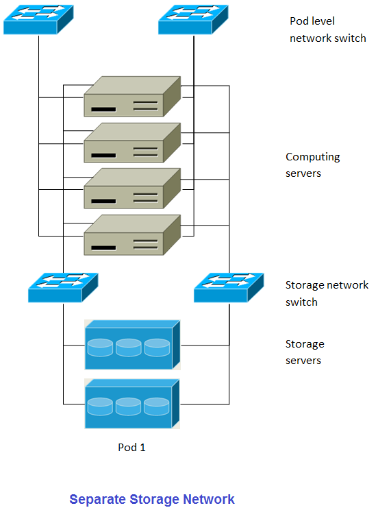
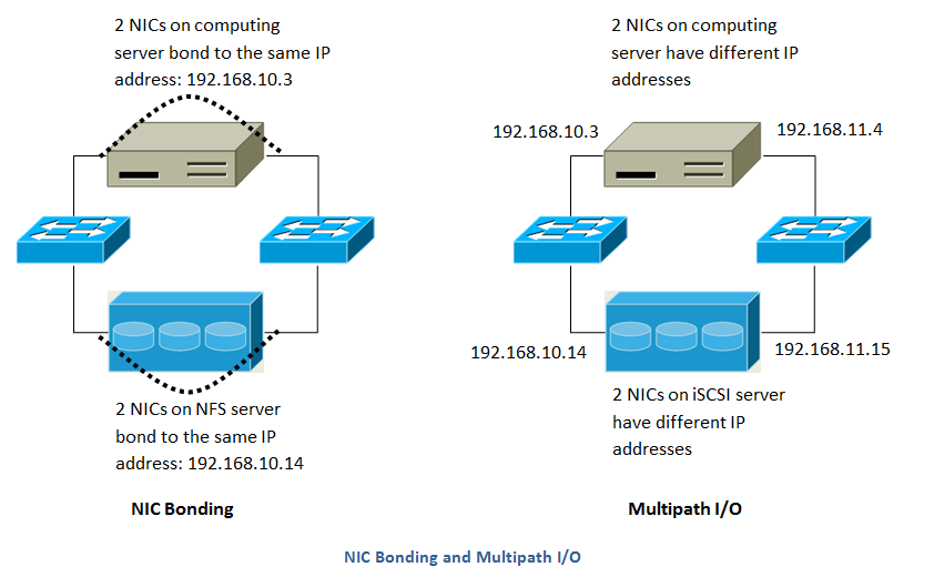
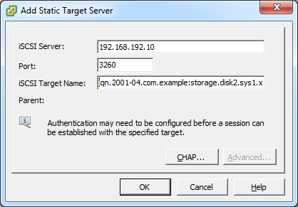
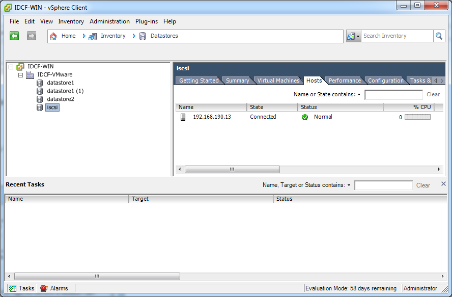
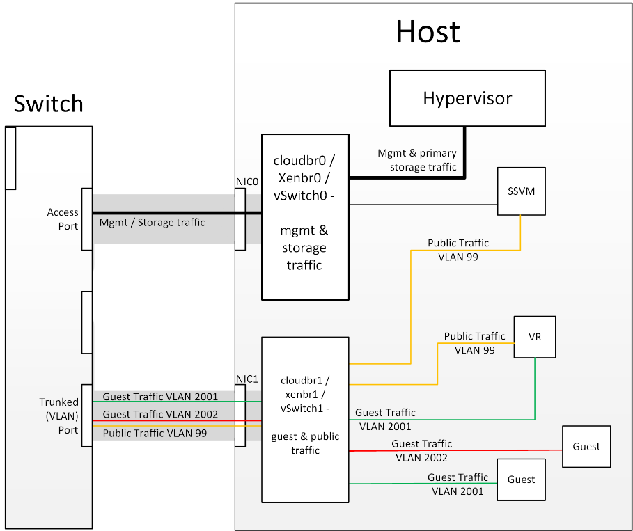
Figure 1: Hypervisor communications

Separating Primary Storage traffic For those from a pure virtualisation background, the concept of creating a specific interface for storage traffic will not be new; it has long been best practice for iSCSI traffic to have a dedicated switch fabric to avoid any latency or contention issues. Sometimes in the cloud(Stack) world we forget that we are simply orchestrating processes that the hypervisors already carry out and that many ‘normal’ hypervisor configurations still apply. The logical reasoning which explains how this splitting of traffic works is as follows:

  1. If you want an additional interface over which the hypervisor can communicate (excluding teamed or bonded interfaces) you need to give it an IP address.
  2. The mechanism to create an additional interface that the hypervisor can use is to create an additional management interface
  3. So that the hypervisor can differentiate between the management interfaces they have to be in different (non-overlapping) subnets
  4. In order for the ‘primary storage’ management interface to communicate with the primary storage, the interfaces on the primary storage arrays must be in the same CIDR as the ‘primary storage’ management interface.
  5. Therefore the primary storage must be in a different subnet to the management network

subnetted storage interfaces 
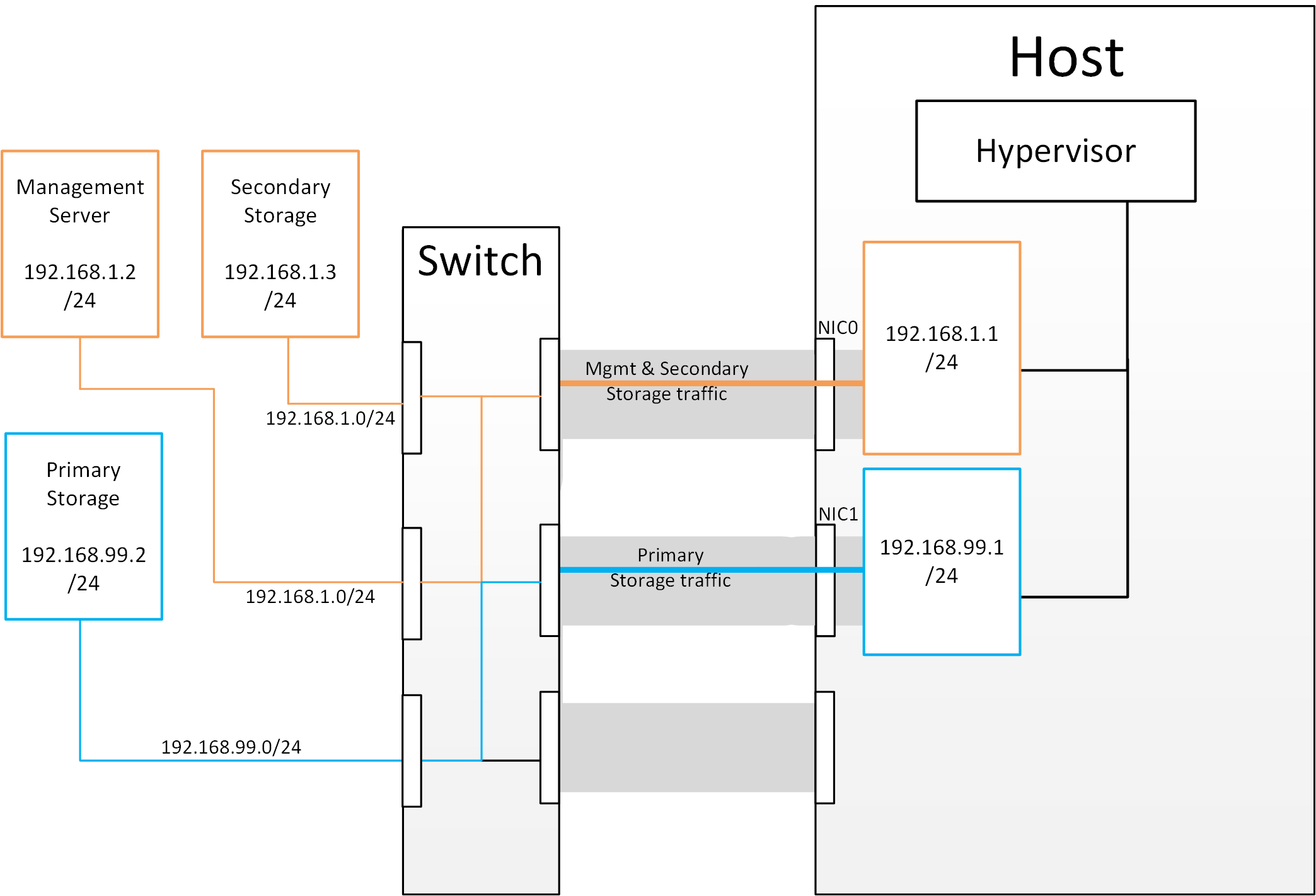
Figure 2: Subnetting of Storage Traffic

hypervisor communications to secondary storage 
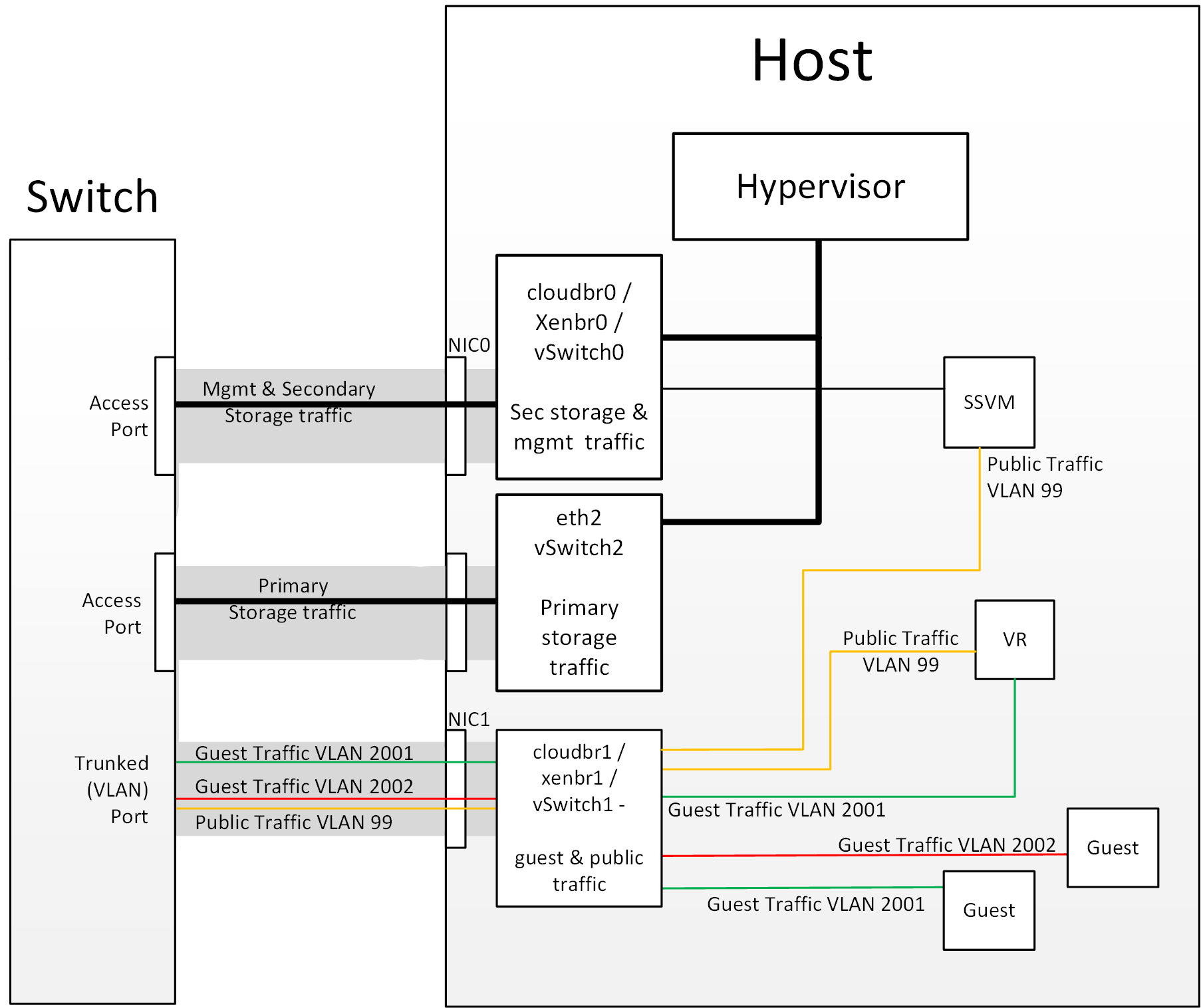
Figure 3: Hypervisor Communications with Separated Storage Traffic

Other Primary Storage Types If you are using PreSetup or SharedMountPoints to connect to IP based storage then the same principles apply; if the primary storage and ‘primary storage interface’ are in a different subnet to the ‘management subnet’ then the hypervisor will use the ‘primary storage interface’ to communicate with the primary storage.

Small-Scale Example Configurations

In this section we go through a few examples of how to set up storage to work properly on a few types of NFS and iSCSI storage systems.

Linux NFS on Local Disks and DAS

This section describes how to configure an NFS export on a standard Linux installation. The exact commands might vary depending on the operating system version.

  1. Install the RHEL/CentOS distribution on the storage server.

  2. If the root volume is more than 2 TB in size, create a smaller boot volume to install RHEL/CentOS. A root volume of 20 GB should be sufficient.

  3. After the system is installed, create a directory called /export. This can each be a directory in the root partition itself or a mount point for a large disk volume.

  4. If you have more than 16TB of storage on one host, create multiple EXT3 file systems and multiple NFS exports. Individual EXT3 file systems cannot exceed 16TB.

  5. After /export directory is created, run the following command to configure it as an NFS export.

    # echo "/export <CIDR>(rw,async,no_root_squash,no_subtree_check)" >> /etc/exports
    

    Adjust the above command to suit your deployment needs.

  • Limiting NFS export. It is highly recommended that you limit the NFS export to a particular subnet by specifying a subnet mask (e.g.,”192.168.1.0/24”). By allowing access from only within the expected cluster, you avoid having non-pool member mount the storage. The limit you place must include the management network(s) and the storage network(s). If the two are the same network then one CIDR is sufficient. If you have a separate storage network you must provide separate CIDR’s for both or one CIDR that is broad enough to span both.

The following is an example with separate CIDRs:

/export 192.168.1.0/24(rw,async,no_root_squash,no_subtree_check) 10.50.1.0/24(rw,async,no_root_squash,no_subtree_check)
  • Removing the async flag. The async flag improves performance by allowing the NFS server to respond before writes are committed to the disk. Remove the async flag in your mission critical production deployment.
  1. Run the following command to enable NFS service.

    # chkconfig nfs on
    
  2. Edit the /etc/sysconfig/nfs file and uncomment the following lines.

    LOCKD_TCPPORT=32803
    LOCKD_UDPPORT=32769
    MOUNTD_PORT=892
    RQUOTAD_PORT=875
    STATD_PORT=662
    STATD_OUTGOING_PORT=2020
    
  3. Edit the /etc/sysconfig/iptables file and add the following lines at the beginning of the INPUT chain.

    -A INPUT -m state --state NEW -p udp --dport 111 -j ACCEPT
    -A INPUT -m state --state NEW -p tcp --dport 111 -j ACCEPT
    -A INPUT -m state --state NEW -p tcp --dport 2049 -j ACCEPT
    -A INPUT -m state --state NEW -p tcp --dport 32803 -j ACCEPT
    -A INPUT -m state --state NEW -p udp --dport 32769 -j ACCEPT
    -A INPUT -m state --state NEW -p tcp --dport 892 -j ACCEPT
    -A INPUT -m state --state NEW -p udp --dport 892 -j ACCEPT
    -A INPUT -m state --state NEW -p tcp --dport 875 -j ACCEPT
    -A INPUT -m state --state NEW -p udp --dport 875 -j ACCEPT
    -A INPUT -m state --state NEW -p tcp --dport 662 -j ACCEPT
    -A INPUT -m state --state NEW -p udp --dport 662 -j ACCEPT
    
  4. Reboot the server.

    An NFS share called /export is now set up.

Note

When copying and pasting a command, be sure the command has pasted as a single line before executing. Some document viewers may introduce unwanted line breaks in copied text.

Linux NFS on iSCSI

Use the following steps to set up a Linux NFS server export on an iSCSI volume. These steps apply to RHEL/CentOS 5 distributions.

  1. Install iscsiadm.

    # yum install iscsi-initiator-utils
    # service iscsi start
    # chkconfig --add iscsi
    # chkconfig iscsi on
    
  2. Discover the iSCSI target.

    # iscsiadm -m discovery -t st -p <iSCSI Server IP address>:3260
    

    For example:

    # iscsiadm -m discovery -t st -p 172.23.10.240:3260 172.23.10.240:3260,1 iqn.2001-05.com.equallogic:0-8a0906-83bcb3401-16e0002fd0a46f3d-rhel5-test
    
  3. Log in.

    # iscsiadm -m node -T <Complete Target Name> -l -p <Group IP>:3260
    

    For example:

    # iscsiadm -m node -l -T iqn.2001-05.com.equallogic:83bcb3401-16e0002fd0a46f3d-rhel5-test -p 172.23.10.240:3260
    
  4. Discover the SCSI disk. For example:

    # iscsiadm -m session -P3 | grep Attached
    Attached scsi disk sdb State: running
    
  5. Format the disk as ext3 and mount the volume.

    # mkfs.ext3 /dev/sdb
    # mkdir -p /export
    # mount /dev/sdb /export
    
  6. Add the disk to /etc/fstab to make sure it gets mounted on boot.

    /dev/sdb /export ext3 _netdev 0 0
    

Now you can set up /export as an NFS share.

  • Limiting NFS export. In order to avoid data loss, it is highly recommended that you limit the NFS export to a particular subnet by specifying a subnet mask (e.g.,”192.168.1.0/24”). By allowing access from only within the expected cluster, you avoid having non-pool member mount the storage and inadvertently delete all its data. The limit you place must include the management network(s) and the storage network(s). If the two are the same network then one CIDR is sufficient. If you have a separate storage network you must provide separate CIDRs for both or one CIDR that is broad enough to span both.

    The following is an example with separate CIDRs:

    /export 192.168.1.0/24(rw,async,no_root_squash,no_subtree_check) 10.50.1.0/24(rw,async,no_root_squash,no_subtree_check)
    
  • Removing the async flag. The async flag improves performance by allowing the NFS server to respond before writes are committed to the disk. Remove the async flag in your mission critical production deployment.

Optional Installation

Additional Installation Options

The next few sections describe CloudStack features above and beyond the basic deployment options.

Installing the Usage Server (Optional)

You can optionally install the Usage Server once the Management Server is configured properly. The Usage Server takes data from the events in the system and enables usage-based billing for accounts.

When multiple Management Servers are present, the Usage Server may be installed on any number of them. The Usage Servers will coordinate usage processing. A site that is concerned about availability should install Usage Servers on at least two Management Servers.

Requirements for Installing the Usage Server
  • The Management Server must be running when the Usage Server is installed.
  • The Usage Server must be installed on the same server as a Management Server.
Steps to Install the Usage Server
  1. Package repository should already being configured. Refer to Configure Package Repository

  2. Install package cloudstack-usage

    On RHEL/CentOS systems, use:

    # yum install cloudstack-usage
    

    On Debian/Ubuntu systems, use:

    # apt-get install cloudstack-usage
    
  3. Once installed, start the Usage Server with the following command.

    # service cloudstack-usage start
    
  4. Enable the service at boot

    On RHEL/CentOS systems, use:

    # chkconfig cloudstack-usage on
    

    On Debian/Ubuntu systems, use:

    # update-rc.d cloudstack-usage defaults
    

The Administration Guide discusses further configuration of the Usage Server.

SSL (Optional)

CloudStack provides HTTP access in its default installation. There are a number of technologies and sites which choose to implement SSL. As a result, we have left CloudStack to expose HTTP under the assumption that a site will implement its typical practice.

CloudStack uses Tomcat as its servlet container. For sites that would like CloudStack to terminate the SSL session, Tomcat’s SSL access may be enabled. Tomcat SSL configuration is described at http://tomcat.apache.org/tomcat-6.0-doc/ssl-howto.html.

Database Replication (Optional)

CloudStack supports database replication from one MySQL node to another. This is achieved using standard MySQL replication. You may want to do this as insurance against MySQL server or storage loss. MySQL replication is implemented using a master/slave model. The master is the node that the Management Servers are configured to use. The slave is a standby node that receives all write operations from the master and applies them to a local, redundant copy of the database. The following steps are a guide to implementing MySQL replication.

Note

Creating a replica is not a backup solution. You should develop a backup procedure for the MySQL data that is distinct from replication.

  1. Ensure that this is a fresh install with no data in the master.

  2. Edit my.cnf on the master and add the following in the [mysqld] section below datadir.

    log_bin=mysql-bin
    server_id=1
    

    The server_id must be unique with respect to other servers. The recommended way to achieve this is to give the master an ID of 1 and each slave a sequential number greater than 1, so that the servers are numbered 1, 2, 3, etc.

  3. Restart the MySQL service. On RHEL/CentOS systems, use:

    # service mysqld restart
    

    On Debian/Ubuntu systems, use:

    # service mysql restart
    
  4. Create a replication account on the master and give it privileges. We will use the “cloud-repl” user with the password “password”. This assumes that master and slave run on the 172.16.1.0/24 network.

    # mysql -u root
    mysql> create user 'cloud-repl'@'172.16.1.%' identified by 'password';
    mysql> grant replication slave on *.* TO 'cloud-repl'@'172.16.1.%';
    mysql> flush privileges;
    mysql> flush tables with read lock;
    
  5. Leave the current MySQL session running.

  6. In a new shell start a second MySQL session.

  7. Retrieve the current position of the database.

    # mysql -u root
    mysql> show master status;
    +------------------+----------+--------------+------------------+
    | File             | Position | Binlog_Do_DB | Binlog_Ignore_DB |
    +------------------+----------+--------------+------------------+
    | mysql-bin.000001 |      412 |              |                  |
    +------------------+----------+--------------+------------------+
    
  8. Note the file and the position that are returned by your instance.

  9. Exit from this session.

  10. Complete the master setup. Returning to your first session on the master, release the locks and exit MySQL.

    mysql> unlock tables;
    
  11. Install and configure the slave. On the slave server, run the following commands.

    # yum install mysql-server
    # chkconfig mysqld on
    
  12. Edit my.cnf and add the following lines in the [mysqld] section below datadir.

    server_id=2
    innodb_rollback_on_timeout=1
    innodb_lock_wait_timeout=600
    
  13. Restart MySQL. Use “mysqld” on RHEL/CentOS systems:

    # service mysqld restart
    

    On Ubuntu/Debian systems use “mysql.”

    # service mysql restart
    
  14. Instruct the slave to connect to and replicate from the master. Replace the IP address, password, log file, and position with the values you have used in the previous steps.

    mysql> change master to
        -> master_host='172.16.1.217',
        -> master_user='cloud-repl',
        -> master_password='password',
        -> master_log_file='mysql-bin.000001',
        -> master_log_pos=412;
    
  15. Then start replication on the slave.

    mysql> start slave;
    
  16. Optionally, open port 3306 on the slave as was done on the master earlier.

    This is not required for replication to work. But if you choose not to do this, you will need to do it when failover to the replica occurs.

Failover

This will provide for a replicated database that can be used to implement manual failover for the Management Servers. CloudStack failover from one MySQL instance to another is performed by the administrator. In the event of a database failure you should:

  1. Stop the Management Servers (via service cloudstack-management stop).

  2. Change the replica’s configuration to be a master and restart it.

  3. Ensure that the replica’s port 3306 is open to the Management Servers.

  4. Make a change so that the Management Server uses the new database. The simplest process here is to put the IP address of the new database server into each Management Server’s /etc/cloudstack/management/db.properties.

  5. Restart the Management Servers:

    # service cloudstack-management start
    

Amazon Web Services Interface

Amazon Web Services Compatible Interface

CloudStack can translate Amazon Web Services (AWS) API calls to native CloudStack API calls so that users can continue using existing AWS-compatible tools. This translation service runs as a separate web application in the same tomcat server as the management server of CloudStack, listening on a different port. The Amazon Web Services (AWS) compatible interface provides the EC2 SOAP and Query APIs as well as the S3 REST API.

Note

This service was previously enabled by separate software called CloudBridge. It is now fully integrated with the CloudStack management server.

Warning

The compatible interface for the EC2 Query API and the S3 API are Work In Progress. The S3 compatible API offers a way to store data on the management server file system, it is not an implementation of the S3 backend.

Limitations

  • Supported only in zones that use basic networking.
  • Available in fresh installations of CloudStack. Not available through upgrade of previous versions.
  • Features such as Elastic IP (EIP) and Elastic Load Balancing (ELB) are only available in an infrastructure with a Citrix NetScaler device. Users accessing a Zone with a NetScaler device will need to use a NetScaler-enabled network offering (DefaultSharedNetscalerEIP and ELBNetworkOffering).
Supported API Version

Note

Work is underway to support a more recent version of the EC2 API

Enabling the EC2 and S3 Compatible Interface

The software that provides AWS API compatibility is installed along with CloudStack. You must enable the services and perform some setup steps prior to using it.

  1. Set the global configuration parameters for each service to true. See *Setting Global Configuration Parameters*.

  2. Create a set of CloudStack service offerings with names that match the Amazon service offerings. You can do this through the CloudStack UI as described in the Administration Guide.

    Warning

    Be sure you have included the Amazon default service offering, m1.small. As well as any EC2 instance types that you will use.

  3. If you did not already do so when you set the configuration parameter in step 1, restart the Management Server.

    # service cloudstack-management restart
    

The following sections provides details to perform these steps

Enabling the Services

To enable the EC2 and S3 compatible services you need to set the configuration variables enable.ec2.api and enable.s3.api to true. You do not have to enable both at the same time. Enable the ones you need. This can be done via the CloudStack GUI by going in Global Settings or via the API.

The snapshot below shows you how to use the GUI to enable these services

Use the GUI to set the configuration variable to true

Using the CloudStack API, the easiest is to use the so-called integration port on which you can make unauthenticated calls. In Global Settings set the port to 8096 and subsequently call the updateConfiguration method. The following urls shows you how:

http://localhost:8096/client/api?command=updateConfiguration&name=enable.ec2.api&value=true

Once you have enabled the services, restart the server.

Creating EC2 Compatible Service Offerings

You will also need to define compute service offerings with names compatible with the Amazon EC2 instance types API names (e.g m1.small,m1.large). This can be done via the CloudStack GUI. Go under Service Offerings select Compute offering and either create a new compute offering or modify an existing one, ensuring that the name matches an EC2 instance type API name. The snapshot below shows you how:

Use the GUI to set the name of a compute service offering to an EC2 instance type API name.

Modifying the AWS API Port

Note

(Optional) The AWS API listens for requests on port 7080. If you prefer AWS API to listen on another port, you can change it as follows:

  1. Edit the files /etc/cloudstack/management/server.xml, /etc/cloudstack/management/server-nonssl.xml, and /etc/cloudstack/management/server-ssl.xml.
  2. In each file, find the tag <Service name=”Catalina7080”>. Under this tag, locate <Connector executor=”tomcatThreadPool-internal” port= ....<.
  3. Change the port to whatever port you want to use, then save the files.
  4. Restart the Management Server.

If you re-install CloudStack, you will have to re-enable the services and if need be update the port.

AWS API User Setup

In general, users need not be aware that they are using a translation service provided by CloudStack. They only need to send AWS API calls to CloudStack’s endpoint, and it will translate the calls to the native CloudStack API. Users of the Amazon EC2 compatible interface will be able to keep their existing EC2 tools and scripts and use them with their CloudStack deployment, by specifying the endpoint of the management server and using the proper user credentials. In order to do this, each user must perform the following configuration steps:

  • Generate user credentials.
  • Register with the service.
  • For convenience, set up environment variables for the EC2 SOAP command-line tools.
AWS API Command-Line Tools Setup

To use the EC2 command-line tools, the user must perform these steps:

  1. Be sure you have the right version of EC2 Tools. The supported version is available at http://s3.amazonaws.com/ec2-downloads/ec2-api-tools-1.3-62308.zip.
  2. Set up the EC2 environment variables. This can be done every time you use the service or you can set them up in the proper shell profile. Replace the endpoint (i.e EC2_URL) with the proper address of your CloudStack management server and port. In a bash shell do the following.
$ export EC2_CERT=/path/to/cert.pem
$ export EC2_PRIVATE_KEY=/path/to/private_key.pem
$ export EC2_URL=http://localhost:7080/awsapi
$ export EC2_HOME=/path/to/EC2_tools_directory
Using Timeouts to Ensure AWS API Command Completion

The Amazon EC2 command-line tools have a default connection timeout. When used with CloudStack, a longer timeout might be needed for some commands. If you find that commands are not completing due to timeouts, you can specify a custom timeouts. You can add the following optional command-line parameters to any CloudStack-supported EC2 command:

Specifies a connection timeout (in seconds)

--connection-timeout TIMEOUT

Specifies a request timeout (in seconds)

--request-timeout TIMEOUT

Example:

ec2-run-instances 2 –z us-test1 –n 1-3 --connection-timeout 120 --request-timeout 120

Note

The timeouts optional arguments are not specific to CloudStack.

Supported AWS API Calls

The following Amazon EC2 commands are supported by CloudStack when the AWS API compatible interface is enabled. For a few commands, there are differences between the CloudStack and Amazon EC2 versions, and these differences are noted. The underlying SOAP call for each command is also given, for those who have built tools using those calls.

Table 1. Elastic IP API mapping

EC2 command SOAP call CloudStack API call
ec2-allocate-address AllocateAddress associateIpAddress
ec2-associate-address AssociateAddress enableStaticNat
ec2-describe-addresses DescribeAddresses listPublicIpAddresses
ec2-diassociate-address DisassociateAddress disableStaticNat
ec2-release-address ReleaseAddress disassociateIpAddress

Table 2. Availability Zone API mapping

EC2 command SOAP call CloudStack API call
ec2-describe-availability-zones DescribeAvailabilityZones listZones

Table 3. Images API mapping

EC2 command SOAP call CloudStack API call
ec2-create-image CreateImage createTemplate
ec2-deregister DeregisterImage DeleteTemplate
ec2-describe-images DescribeImages listTemplates
ec2-register RegisterImage registerTemplate

Table 4. Image Attributes API mapping

EC2 command SOAP call CloudStack API call
ec2-describe-image-attribute DescribeImageAttribute listTemplatePermissions
ec2-modify-image-attribute ModifyImageAttribute updateTemplatePermissions
ec2-reset-image-attribute ResetImageAttribute updateTemplatePermissions

Table 5. Instances API mapping

EC2 command SOAP call CloudStack API call
ec2-describe-instances DescribeInstances listVirtualMachines
ec2-run-instances RunInstances deployVirtualMachine
ec2-reboot-instances RebootInstances rebootVirtualMachine
ec2-start-instances StartInstances startVirtualMachine
ec2-stop-instances StopInstances stopVirtualMachine
ec2-terminate-instances TerminateInstances destroyVirtualMachine

Table 6. Instance Attributes Mapping

EC2 command SOAP call CloudStack API call
ec2-describe-instance-attribute DescribeInstanceAttribute listVirtualMachines

Table 7. Keys Pairs Mapping

EC2 command SOAP call CloudStack API call
ec2-add-keypair CreateKeyPair createSSHKeyPair
ec2-delete-keypair DeleteKeyPair deleteSSHKeyPair
ec2-describe-keypairs DescribeKeyPairs listSSHKeyPairs
ec2-import-keypair ImportKeyPair registerSSHKeyPair

Table 8. Passwords API Mapping

EC2 command SOAP call CloudStack API call
ec2-get-password GetPasswordData getVMPassword

Table 9. Security Groups API Mapping

EC2 command SOAP call CloudStack API call
ec2-authorize AuthorizeSecurityGroupIngress authorizeSecurityGroupIngress
ec2-add-group CreateSecurityGroup createSecurityGroup
ec2-delete-group DeleteSecurityGroup deleteSecurityGroup
ec2-describe-group DescribeSecurityGroups listSecurityGroups
ec2-revoke RevokeSecurityGroupIngress revokeSecurityGroupIngress

Table 10. Snapshots API Mapping

EC2 command SOAP call CloudStack API call
ec2-create-snapshot CreateSnapshot createSnapshot
ec2-delete-snapshot DeleteSnapshot deleteSnapshot
ec2-describe-snapshots DescribeSnapshots listSnapshots

Table 11. Volumes API Mapping

EC2 command SOAP call CloudStack API call
ec2-attach-volume AttachVolume attachVolume
ec2-create-volume CreateVolume createVolume
ec2-delete-volume DeleteVolume deleteVolume
ec2-describe-volume DescribeVolume listVolumes
ec2-detach-volume DetachVolume detachVolume

Examples

There are many tools available to interface with a AWS compatible API. In this section we provide a few examples that users of CloudStack can build upon.

Boto Examples

Boto is one of them. It is a Python package available at https://github.com/boto/boto. In this section we provide two examples of Python scripts that use Boto and have been tested with the CloudStack AWS API Interface.

First is an EC2 example. Replace the Access and Secret Keys with your own and update the endpoint.

Example 1. An EC2 Boto example

#!/usr/bin/env python

import sys
import os
import boto
import boto.ec2

region = boto.ec2.regioninfo.RegionInfo(name="ROOT",endpoint="localhost")
apikey='GwNnpUPrO6KgIdZu01z_ZhhZnKjtSdRwuYd4DvpzvFpyxGMvrzno2q05MB0ViBoFYtdqKd'
secretkey='t4eXLEYWw7chBhDlaKf38adCMSHx_wlds6JfSx3z9fSpSOm0AbP9Moj0oGIzy2LSC8iw'

def main():
    '''Establish connection to EC2 cloud'''
    conn = boto.connect_ec2(aws_access_key_id=apikey,
                            aws_secret_access_key=secretkey,
                            is_secure=False,
                            region=region,
                            port=7080,
                            path="/awsapi",
                            api_version="2010-11-15")

    '''Get list of images that I own'''
    images = conn.get_all_images()
    print images
    myimage = images[0]
    '''Pick an instance type'''
    vm_type='m1.small'
    reservation = myimage.run(instance_type=vm_type,security_groups=['default'])

if __name__ == '__main__':
     main()

Second is an S3 example. The S3 interface in CloudStack is obsolete. If you need an S3 interface you should look at systems like RiakCS, Ceph or GlusterFS. This example is here for completeness and can be adapted to other S3 endpoint.

Example 2. An S3 Boto Example

#!/usr/bin/env python

import sys
import os
from boto.s3.key import Key
from boto.s3.connection import S3Connection
from boto.s3.connection import OrdinaryCallingFormat

apikey='ChOw-pwdcCFy6fpeyv6kUaR0NnhzmG3tE7HLN2z3OB_s-ogF5HjZtN4rnzKnq2UjtnHeg_yLA5gOw'
secretkey='IMY8R7CJQiSGFk4cHwfXXN3DUFXz07cCiU80eM3MCmfLs7kusgyOfm0g9qzXRXhoAPCH-IRxXc3w'

cf=OrdinaryCallingFormat()

def main():
    '''Establish connection to S3 service'''
    conn = S3Connection(aws_access_key_id=apikey,aws_secret_access_key=secretkey, \
                        is_secure=False, \
                        host='localhost', \
                        port=7080, \
                        calling_format=cf, \
                        path="/awsapi/rest/AmazonS3")

    try:
        bucket=conn.create_bucket('cloudstack')
        k = Key(bucket)
        k.key = 'test'
        try:
            k.set_contents_from_filename('/Users/runseb/Desktop/s3cs.py')
        except:
            print 'could not write file'
            pass
    except:
        bucket = conn.get_bucket('cloudstack')
        k = Key(bucket)
        k.key = 'test'
        try:
            k.get_contents_to_filename('/Users/runseb/Desktop/foobar')
        except:
            print 'Could not get file'
            pass

    try:
        bucket1=conn.create_bucket('teststring')
        k=Key(bucket1)
        k.key('foobar')
        k.set_contents_from_string('This is my silly test')
    except:
        bucket1=conn.get_bucket('teststring')
        k = Key(bucket1)
        k.key='foobar'
        k.get_contents_as_string()

if __name__ == '__main__':
    main()

About Password and Key Encryption

CloudStack stores several sensitive passwords and secret keys that are used to provide security. These values are always automatically encrypted:

  • Database secret key
  • Database password
  • SSH keys
  • Compute node root password
  • VPN password
  • User API secret key
  • VNC password

CloudStack uses the Java Simplified Encryption (JASYPT) library. The data values are encrypted and decrypted using a database secret key, which is stored in one of CloudStack’s internal properties files along with the database password. The other encrypted values listed above, such as SSH keys, are in the CloudStack internal database.

Of course, the database secret key itself can not be stored in the open – it must be encrypted. How then does CloudStack read it? A second secret key must be provided from an external source during Management Server startup. This key can be provided in one of two ways: loaded from a file or provided by the CloudStack administrator. The CloudStack database has a configuration setting that lets it know which of these methods will be used. If the encryption type is set to “file,” the key must be in a file in a known location. If the encryption type is set to “web,” the administrator runs the utility com.cloud.utils.crypt.EncryptionSecretKeySender, which relays the key to the Management Server over a known port.

The encryption type, database secret key, and Management Server secret key are set during CloudStack installation. They are all parameters to the CloudStack database setup script (cloudstack-setup-databases). The default values are file, password, and password. It is, of course, highly recommended that you change these to more secure keys.

Changing the Default Password Encryption

Passwords are encoded when creating or updating users. CloudStack allows you to determine the default encoding and authentication mechanism for admin and user logins. Two new configurable lists have been introduced—userPasswordEncoders and userAuthenticators. userPasswordEncoders allows you to configure the order of preference for encoding passwords, whereas userAuthenticators allows you to configure the order in which authentication schemes are invoked to validate user passwords.

Additionally, the plain text user authenticator has been modified not to convert supplied passwords to their md5 sums before checking them with the database entries. It performs a simple string comparison between retrieved and supplied login passwords instead of comparing the retrieved md5 hash of the stored password against the supplied md5 hash of the password because clients no longer hash the password. The following method determines what encoding scheme is used to encode the password supplied during user creation or modification.

When a new user is created, the user password is encoded by using the first valid encoder loaded as per the sequence specified in the UserPasswordEncoders property in the ComponentContext.xml or nonossComponentContext.xml files. The order of authentication schemes is determined by the UserAuthenticators property in the same files. If Non-OSS components, such as VMware environments, are to be deployed, modify the UserPasswordEncoders and UserAuthenticators lists in the nonossComponentContext.xml file, for OSS environments, such as XenServer or KVM, modify the ComponentContext.xml file. It is recommended to make uniform changes across both the files. When a new authenticator or encoder is added, you can add them to this list. While doing so, ensure that the new authenticator or encoder is specified as a bean in both these files. The administrator can change the ordering of both these properties as preferred to change the order of schemes. Modify the following list properties available in client/tomcatconf/nonossComponentContext.xml.in or client/tomcatconf/componentContext.xml.in as applicable, to the desired order:

<property name="UserAuthenticators">
   <list>
      <ref bean="SHA256SaltedUserAuthenticator"/>
      <ref bean="MD5UserAuthenticator"/>
      <ref bean="LDAPUserAuthenticator"/>
      <ref bean="PlainTextUserAuthenticator"/>
   </list>
</property>
<property name="UserPasswordEncoders">
   <list>
      <ref bean="SHA256SaltedUserAuthenticator"/>
      <ref bean="MD5UserAuthenticator"/>
      <ref bean="LDAPUserAuthenticator"/>
      <ref bean="PlainTextUserAuthenticator"/>
   </list>
</property>

In the above default ordering, SHA256Salt is used first for UserPasswordEncoders. If the module is found and encoding returns a valid value, the encoded password is stored in the user table’s password column. If it fails for any reason, the MD5UserAuthenticator will be tried next, and the order continues. For UserAuthenticators, SHA256Salt authentication is tried first. If it succeeds, the user is logged into the Management server. If it fails, md5 is tried next, and attempts continues until any of them succeeds and the user logs in . If none of them works, the user is returned an invalid credential message.