Managing Networks and Traffic
In a CloudStack, guest VMs can communicate with each other using shared
infrastructure with the security and user perception that the guests
have a private LAN. The CloudStack virtual router is the main component
providing networking features for guest traffic.
Guest Traffic
A network can carry guest traffic only between VMs within one zone.
Virtual machines in different zones cannot communicate with each other
using their IP addresses; they must communicate with each other by
routing through a public IP address.
See a typical guest traffic setup given below:
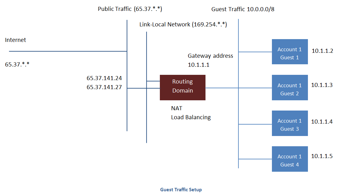
Typically, the Management Server automatically creates a virtual router
for each network. A virtual router is a special virtual machine that
runs on the hosts. Each virtual router in an isolated network has three
network interfaces. If multiple public VLAN is used, the router will
have multiple public interfaces. Its eth0 interface serves as the
gateway for the guest traffic and has the IP address of 10.1.1.1. Its
eth1 interface is used by the system to configure the virtual router.
Its eth2 interface is assigned a public IP address for public traffic.
If multiple public VLAN is used, the router will have multiple public
interfaces.
The virtual router provides DHCP and will automatically assign an IP
address for each guest VM within the IP range assigned for the network.
The user can manually reconfigure guest VMs to assume different IP
addresses.
Source NAT is automatically configured in the virtual router to forward
outbound traffic for all guest VMs
Networking in a Pod
The figure below illustrates network setup within a single pod. The
hosts are connected to a pod-level switch. At a minimum, the hosts
should have one physical uplink to each switch. Bonded NICs are
supported as well. The pod-level switch is a pair of redundant gigabit
switches with 10 G uplinks.
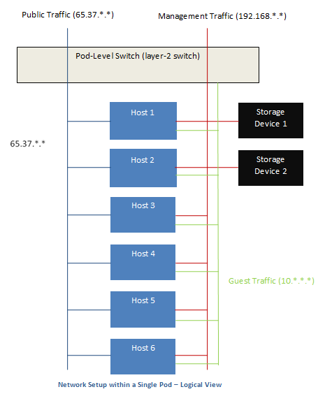
Servers are connected as follows:
- Storage devices are connected to only the network that carries
management traffic.
- Hosts are connected to networks for both management traffic and
public traffic.
- Hosts are also connected to one or more networks carrying guest
traffic.
We recommend the use of multiple physical Ethernet cards to implement
each network interface as well as redundant switch fabric in order to
maximize throughput and improve reliability.
Networking in a Zone
The following figure illustrates the network setup within a single zone.
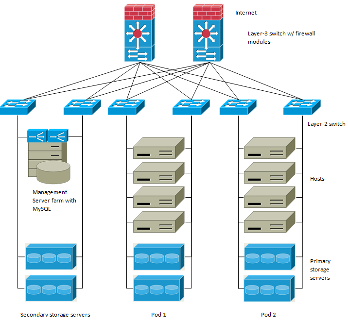
A firewall for management traffic operates in the NAT mode. The network
typically is assigned IP addresses in the 192.168.0.0/16 Class B private
address space. Each pod is assigned IP addresses in the 192.168.*.0/24
Class C private address space.
Each zone has its own set of public IP addresses. Public IP addresses
from different zones do not overlap.
Basic Zone Physical Network Configuration
In a basic network, configuring the physical network is fairly
straightforward. You only need to configure one guest network to carry
traffic that is generated by guest VMs. When you first add a zone to
CloudStack, you set up the guest network through the Add Zone screens.
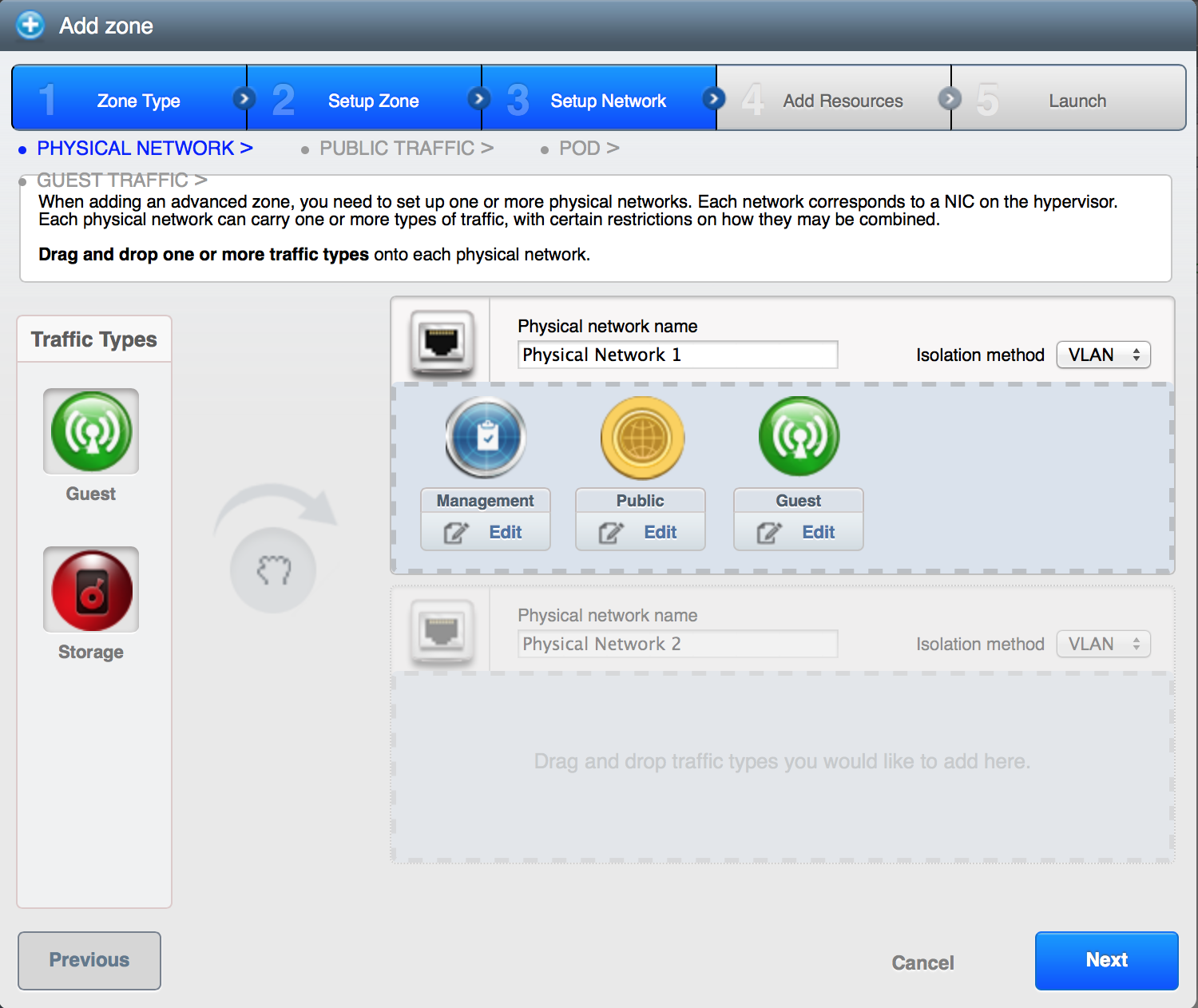
Advanced Zone Physical Network Configuration
Within a zone that uses advanced networking, you need to tell the
Management Server how the physical network is set up to carry different
kinds of traffic in isolation.
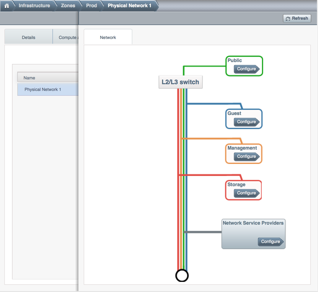
Configuring a Shared Guest Network
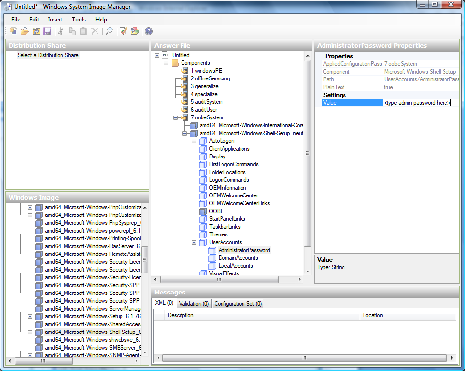
Log in to the CloudStack UI as administrator.
In the left navigation, choose Infrastructure.
On Zones, click View More.
Click the zone to which you want to add a guest network.
Click the Physical Network tab.
Click the physical network you want to work with.
On the Guest node of the diagram, click Configure.
Click the Network tab.
Click Add guest network.
The Add guest network window is displayed.
Specify the following:
Name: The name of the network. This will be visible to the user.
Description: The short description of the network that can be
displayed to users.
VLAN ID: The unique ID of the VLAN.
Isolated VLAN ID: The unique ID of the Secondary Isolated
VLAN.
Scope: The available scopes are Domain, Account, Project, and
All.
- Domain: Selecting Domain limits the scope of this guest
network to the domain you specify. The network will not be
available for other domains. If you select Subdomain Access,
the guest network is available to all the sub domains within
the selected domain.
- Account: The account for which the guest network is being
created for. You must specify the domain the account belongs
to.
- Project: The project for which the guest network is being
created for. You must specify the domain the project belongs
to.
- All: The guest network is available for all the domains,
account, projects within the selected zone.
Network Offering: If the administrator has configured multiple
network offerings, select the one you want to use for this
network.
Gateway: The gateway that the guests should use.
Netmask: The netmask in use on the subnet the guests will use.
IP Range: A range of IP addresses that are accessible from the
Internet and are assigned to the guest VMs.
If one NIC is used, these IPs should be in the same CIDR in the
case of IPv6.
IPv6 CIDR: The network prefix that defines the guest network
subnet. This is the CIDR that describes the IPv6 addresses in use
in the guest networks in this zone. To allot IP addresses from
within a particular address block, enter a CIDR.
Network Domain: A custom DNS suffix at the level of a network.
If you want to assign a special domain name to the guest VM
network, specify a DNS suffix.
Click OK to confirm.
Using Multiple Guest Networks
In zones that use advanced networking, additional networks for guest
traffic may be added at any time after the initial installation. You can
also customize the domain name associated with the network by specifying
a DNS suffix for each network.
A VM’s networks are defined at VM creation time. A VM cannot add or
remove networks after it has been created, although the user can go into
the guest and remove the IP address from the NIC on a particular
network.
Each VM has just one default network. The virtual router’s DHCP reply
will set the guest’s default gateway as that for the default network.
Multiple non-default networks may be added to a guest in addition to the
single, required default network. The administrator can control which
networks are available as the default network.
Additional networks can either be available to all accounts or be
assigned to a specific account. Networks that are available to all
accounts are zone-wide. Any user with access to the zone can create a VM
with access to that network. These zone-wide networks provide little or
no isolation between guests.Networks that are assigned to a specific
account provide strong isolation.
Adding an Additional Guest Network
- Log in to the CloudStack UI as an administrator or end user.
- In the left navigation, choose Network.
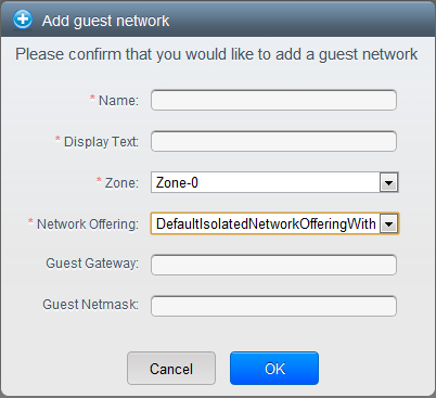
- Click Add guest network. Provide the following information:
- Name: The name of the network. This will be user-visible.
- Display Text: The description of the network. This will be
user-visible.
- Zone. The name of the zone this network applies to. Each zone
is a broadcast domain, and therefore each zone has a different IP
range for the guest network. The administrator must configure the
IP range for each zone.
- Network offering: If the administrator has configured multiple
network offerings, select the one you want to use for this
network.
- Guest Gateway: The gateway that the guests should use.
- Guest Netmask: The netmask in use on the subnet the guests
will use.
- Click Create.
Reconfiguring Networks in VMs
CloudStack provides you the ability to move VMs between networks and
reconfigure a VM’s network. You can remove a VM from a network and add
to a new network. You can also change the default network of a virtual
machine. With this functionality, hybrid or traditional server loads can
be accommodated with ease.
This feature is supported on XenServer, VMware, and KVM hypervisors.
Prerequisites
Ensure that vm-tools are running on guest VMs for adding or removing
networks to work on VMware hypervisor.
Adding a Network
Log in to the CloudStack UI as an administrator or end user.
In the left navigation, click Instances.
Choose the VM that you want to work with.
Click the NICs tab.
Click Add network to VM.
The Add network to VM dialog is displayed.
In the drop-down list, select the network that you would like to add
this VM to.
A new NIC is added for this network. You can view the following
details in the NICs page:
- ID
- Network Name
- Type
- IP Address
- Gateway
- Netmask
- Is default
- CIDR (for IPv6)
Removing a Network
- Log in to the CloudStack UI as an administrator or end user.
- In the left navigation, click Instances.
- Choose the VM that you want to work with.
- Click the NICs tab.
- Locate the NIC you want to remove.
- Click Remove NIC button.

- Click Yes to confirm.
Selecting the Default Network
- Log in to the CloudStack UI as an administrator or end user.
- In the left navigation, click Instances.
- Choose the VM that you want to work with.
- Click the NICs tab.
- Locate the NIC you want to work with.
- Click the Set default NIC button.
 .
.
- Click Yes to confirm.
Changing the Network Offering on a Guest Network
A user or administrator can change the network offering that is
associated with an existing guest network.
Log in to the CloudStack UI as an administrator or end user.
If you are changing from a network offering that uses the CloudStack
virtual router to one that uses external devices as network service
providers, you must first stop all the VMs on the network.
In the left navigation, choose Network.
Click the name of the network you want to modify.
In the Details tab, click Edit. 
In Network Offering, choose the new network offering, then click
Apply.
A prompt is displayed asking whether you want to keep the existing
CIDR. This is to let you know that if you change the network
offering, the CIDR will be affected.
If you upgrade between virtual router as a provider and an external
network device as provider, acknowledge the change of CIDR to
continue, so choose Yes.
Wait for the update to complete. Don’t try to restart VMs until the
network change is complete.
If you stopped any VMs, restart them.
IP Reservation in Isolated Guest Networks
In isolated guest networks, a part of the guest IP address space can be
reserved for non-CloudStack VMs or physical servers. To do so, you
configure a range of Reserved IP addresses by specifying the CIDR when a
guest network is in Implemented state. If your customers wish to have
non-CloudStack controlled VMs or physical servers on the same network,
they can share a part of the IP address space that is primarily provided
to the guest network.
In an Advanced zone, an IP address range or a CIDR is assigned to a
network when the network is defined. The CloudStack virtual router acts
as the DHCP server and uses CIDR for assigning IP addresses to the guest
VMs. If you decide to reserve CIDR for non-CloudStack purposes, you can
specify a part of the IP address range or the CIDR that should only be
allocated by the DHCP service of the virtual router to the guest VMs
created in CloudStack. The remaining IPs in that network are called
Reserved IP Range. When IP reservation is configured, the administrator
can add additional VMs or physical servers that are not part of
CloudStack to the same network and assign them the Reserved IP
addresses. CloudStack guest VMs cannot acquire IPs from the Reserved IP
Range.
IP Reservation Considerations
Consider the following before you reserve an IP range for non-CloudStack
machines:
IP Reservation is supported only in Isolated networks.
IP Reservation can be applied only when the network is in Implemented
state.
No IP Reservation is done by default.
Guest VM CIDR you specify must be a subset of the network CIDR.
Specify a valid Guest VM CIDR. IP Reservation is applied only if no
active IPs exist outside the Guest VM CIDR.
You cannot apply IP Reservation if any VM is alloted with an IP
address that is outside the Guest VM CIDR.
To reset an existing IP Reservation, apply IP reservation by
specifying the value of network CIDR in the CIDR field.
For example, the following table describes three scenarios of guest
network creation:
| Case |
CIDR |
Network CIDR |
Reserved IP Range for Non-CloudStack VMs |
Description |
|---|
| 1 |
10.1.1.0/24 |
None |
None |
No IP Reservation. |
| 2 |
10.1.1.0/26 |
10.1.1.0/24 |
10.1.1.64 to 10.1.1.254 |
IP Reservation configured by the UpdateNetwork API with
guestvmcidr=10.1.1.0/26 or enter 10.1.1.0/26 in the CIDR
field in the UI. |
| 3 |
10.1.1.0/24 |
None |
None |
Removing IP Reservation by the UpdateNetwork API with
guestvmcidr=10.1.1.0/24 or enter 10.1.1.0/24 in the CIDR
field in the UI. |
Limitations
- The IP Reservation is not supported if active IPs that are found
outside the Guest VM CIDR.
- Upgrading network offering which causes a change in CIDR (such as
upgrading an offering with no external devices to one with external
devices) IP Reservation becomes void if any. Reconfigure IP
Reservation in the new re-implemeted network.
Best Practices
Apply IP Reservation to the guest network as soon as the network state
changes to Implemented. If you apply reservation soon after the first
guest VM is deployed, lesser conflicts occurs while applying
reservation.
Reserving an IP Range
Log in to the CloudStack UI as an administrator or end user.
In the left navigation, choose Network.
Click the name of the network you want to modify.
In the Details tab, click Edit.
The CIDR field changes to editable one.
In CIDR, specify the Guest VM CIDR.
Click Apply.
Wait for the update to complete. The Network CIDR and the Reserved IP
Range are displayed on the Details page.
Reserving Public IP Addresses and VLANs for Accounts
CloudStack provides you the ability to reserve a set of public IP
addresses and VLANs exclusively for an account. During zone creation,
you can continue defining a set of VLANs and multiple public IP ranges.
This feature extends the functionality to enable you to dedicate a fixed
set of VLANs and guest IP addresses for a tenant.
Note that if an account has consumed all the VLANs and IPs dedicated to
it, the account can acquire two more resources from the system.
CloudStack provides the root admin with two configuration parameter to
modify this default behavior: use.system.public.ips and
use.system.guest.vlans. These global parameters enable the root admin to
disallow an account from acquiring public IPs and guest VLANs from the
system, if the account has dedicated resources and these dedicated
resources have all been consumed. Both these configurations are
configurable at the account level.
This feature provides you the following capabilities:
Reserve a VLAN range and public IP address range from an Advanced
zone and assign it to an account
Disassociate a VLAN and public IP address range from an account
View the number of public IP addresses allocated to an account
Check whether the required range is available and is conforms to
account limits.
The maximum IPs per account limit cannot be superseded.
Dedicating IP Address Ranges to an Account
Log in to the CloudStack UI as administrator.
In the left navigation bar, click Infrastructure.
In Zones, click View All.
Choose the zone you want to work with.
Click the Physical Network tab.
In the Public node of the diagram, click Configure.
Click the IP Ranges tab.
You can either assign an existing IP range to an account, or create a
new IP range and assign to an account.
To assign an existing IP range to an account, perform the following:
Locate the IP range you want to work with.
Click Add Account  button.
The Add Account dialog is displayed.
Specify the following:
- Account: The account to which you want to assign the IP
address range.
- Domain: The domain associated with the account.
To create a new IP range and assign an account, perform the
following:
Specify the following:
Click Add.
Dedicating VLAN Ranges to an Account
After the CloudStack Management Server is installed, log in to the
CloudStack UI as administrator.
In the left navigation bar, click Infrastructure.
In Zones, click View All.
Choose the zone you want to work with.
Click the Physical Network tab.
In the Guest node of the diagram, click Configure.
Select the Dedicated VLAN Ranges tab.
Click Dedicate VLAN Range.
The Dedicate VLAN Range dialog is displayed.
Specify the following:
- VLAN Range: The VLAN range that you want to assign to an
account.
- Account: The account to which you want to assign the
selected VLAN range.
- Domain: The domain associated with the account.
Configuring Multiple IP Addresses on a Single NIC
CloudStack provides you the ability to associate multiple private IP
addresses per guest VM NIC. In addition to the primary IP, you can
assign additional IPs to the guest VM NIC. This feature is supported on
all the network configurations: Basic, Advanced, and VPC. Security
Groups, Static NAT and Port forwarding services are supported on these
additional IPs.
As always, you can specify an IP from the guest subnet; if not
specified, an IP is automatically picked up from the guest VM subnet.
You can view the IPs associated with for each guest VM NICs on the UI.
You can apply NAT on these additional guest IPs by using network
configuration option in the CloudStack UI. You must specify the NIC to
which the IP should be associated.
This feature is supported on XenServer, KVM, and VMware hypervisors.
Note that Basic zone security groups are not supported on VMware.
Use Cases
Some of the use cases are described below:
- Network devices, such as firewalls and load balancers, generally work
best when they have access to multiple IP addresses on the network
interface.
- Moving private IP addresses between interfaces or instances.
Applications that are bound to specific IP addresses can be moved
between instances.
- Hosting multiple SSL Websites on a single instance. You can install
multiple SSL certificates on a single instance, each associated with
a distinct IP address.
Guidelines
To prevent IP conflict, configure different subnets when multiple
networks are connected to the same VM.
Assigning Additional IPs to a VM
Log in to the CloudStack UI.
In the left navigation bar, click Instances.
Click the name of the instance you want to work with.
In the Details tab, click NICs.
Click View Secondary IPs.
Click Acquire New Secondary IP, and click Yes in the confirmation
dialog.
You need to configure the IP on the guest VM NIC manually. CloudStack
will not automatically configure the acquired IP address on the VM.
Ensure that the IP address configuration persist on VM reboot.
Within a few moments, the new IP address should appear with the state
Allocated. You can now use the IP address in Port Forwarding or
StaticNAT rules.
Port Forwarding and StaticNAT Services Changes
Because multiple IPs can be associated per NIC, you are allowed to
select a desired IP for the Port Forwarding and StaticNAT services. The
default is the primary IP. To enable this functionality, an extra
optional parameter ‘vmguestip’ is added to the Port forwarding and
StaticNAT APIs (enableStaticNat, createIpForwardingRule) to indicate on
what IP address NAT need to be configured. If vmguestip is passed, NAT
is configured on the specified private IP of the VM. if not passed, NAT
is configured on the primary IP of the VM.
About Multiple IP Ranges
Note
The feature can only be implemented on IPv4 addresses.
CloudStack provides you with the flexibility to add guest IP ranges from
different subnets in Basic zones and security groups-enabled Advanced
zones. For security groups-enabled Advanced zones, it implies multiple
subnets can be added to the same VLAN. With the addition of this
feature, you will be able to add IP address ranges from the same subnet
or from a different one when IP address are exhausted. This would in
turn allows you to employ higher number of subnets and thus reduce the
address management overhead. To support this feature, the capability of
createVlanIpRange API is extended to add IP ranges also from a
different subnet.
Ensure that you manually configure the gateway of the new subnet before
adding the IP range. Note that CloudStack supports only one gateway for
a subnet; overlapping subnets are not currently supported.
Use the deleteVlanRange API to delete IP ranges. This operation
fails if an IP from the remove range is in use. If the remove range
contains the IP address on which the DHCP server is running, CloudStack
acquires a new IP from the same subnet. If no IP is available in the
subnet, the remove operation fails.
This feature is supported on KVM, xenServer, and VMware hypervisors.
About Elastic IPs
Elastic IP (EIP) addresses are the IP addresses that are associated with
an account, and act as static IP addresses. The account owner has the
complete control over the Elastic IP addresses that belong to the
account. As an account owner, you can allocate an Elastic IP to a VM of
your choice from the EIP pool of your account. Later if required you can
reassign the IP address to a different VM. This feature is extremely
helpful during VM failure. Instead of replacing the VM which is down,
the IP address can be reassigned to a new VM in your account.
Similar to the public IP address, Elastic IP addresses are mapped to
their associated private IP addresses by using StaticNAT. The EIP
service is equipped with StaticNAT (1:1) service in an EIP-enabled basic
zone. The default network offering,
DefaultSharedNetscalerEIPandELBNetworkOffering, provides your network
with EIP and ELB network services if a NetScaler device is deployed in
your zone. Consider the following illustration for more details.
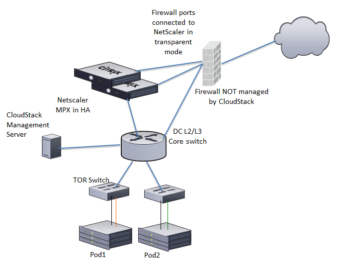
In the illustration, a NetScaler appliance is the default entry or exit
point for the CloudStack instances, and firewall is the default entry or
exit point for the rest of the data center. Netscaler provides LB
services and staticNAT service to the guest networks. The guest traffic
in the pods and the Management Server are on different subnets / VLANs.
The policy-based routing in the data center core switch sends the public
traffic through the NetScaler, whereas the rest of the data center goes
through the firewall.
The EIP work flow is as follows:
When a user VM is deployed, a public IP is automatically acquired
from the pool of public IPs configured in the zone. This IP is owned
by the VM’s account.
Each VM will have its own private IP. When the user VM starts, Static
NAT is provisioned on the NetScaler device by using the Inbound
Network Address Translation (INAT) and Reverse NAT (RNAT) rules
between the public IP and the private IP.
Note
Inbound NAT (INAT) is a type of NAT supported by NetScaler, in which
the destination IP address is replaced in the packets from the public
network, such as the Internet, with the private IP address of a VM in
the private network. Reverse NAT (RNAT) is a type of NAT supported by
NetScaler, in which the source IP address is replaced in the packets
generated by a VM in the private network with the public IP address.
This default public IP will be released in two cases:
- When the VM is stopped. When the VM starts, it again receives a
new public IP, not necessarily the same one allocated initially,
from the pool of Public IPs.
- The user acquires a public IP (Elastic IP). This public IP is
associated with the account, but will not be mapped to any private
IP. However, the user can enable Static NAT to associate this IP
to the private IP of a VM in the account. The Static NAT rule for
the public IP can be disabled at any time. When Static NAT is
disabled, a new public IP is allocated from the pool, which is not
necessarily be the same one allocated initially.
For the deployments where public IPs are limited resources, you have the
flexibility to choose not to allocate a public IP by default. You can
use the Associate Public IP option to turn on or off the automatic
public IP assignment in the EIP-enabled Basic zones. If you turn off the
automatic public IP assignment while creating a network offering, only a
private IP is assigned to a VM when the VM is deployed with that network
offering. Later, the user can acquire an IP for the VM and enable static
NAT.
For more information on the Associate Public IP option, see
“Creating a New Network Offering”.
Note
The Associate Public IP feature is designed only for use with user VMs.
The System VMs continue to get both public IP and private by default,
irrespective of the network offering configuration.
New deployments which use the default shared network offering with EIP
and ELB services to create a shared network in the Basic zone will
continue allocating public IPs to each user VM.
Portable IPs
About Portable IP
Portable IPs in CloudStack are region-level pool of IPs, which are
elastic in nature, that can be transferred across geographically
separated zones. As an administrator, you can provision a pool of
portable public IPs at region level and are available for user
consumption. The users can acquire portable IPs if admin has provisioned
portable IPs at the region level they are part of. These IPs can be use
for any service within an advanced zone. You can also use portable IPs
for EIP services in basic zones.
The salient features of Portable IP are as follows:
- IP is statically allocated
- IP need not be associated with a network
- IP association is transferable across networks
- IP is transferable across both Basic and Advanced zones
- IP is transferable across VPC, non-VPC isolated and shared networks
- Portable IP transfer is available only for static NAT.
Guidelines
Before transferring to another network, ensure that no network rules
(Firewall, Static NAT, Port Forwarding, and so on) exist on that
portable IP.
Configuring Portable IPs
Log in to the CloudStack UI as an administrator or end user.
In the left navigation, click Regions.
Choose the Regions that you want to work with.
Click View Portable IP.
Click Portable IP Range.
The Add Portable IP Range window is displayed.
Specify the following:
- Start IP/ End IP: A range of IP addresses that are accessible
from the Internet and will be allocated to guest VMs. Enter the
first and last IP addresses that define a range that CloudStack
can assign to guest VMs.
- Gateway: The gateway in use for the Portable IP addresses you
are configuring.
- Netmask: The netmask associated with the Portable IP range.
- VLAN: The VLAN that will be used for public traffic.
Click OK.
Acquiring a Portable IP
Log in to the CloudStack UI as an administrator or end user.
In the left navigation, choose Network.
Click the name of the network where you want to work with.
Click View IP Addresses.
Click Acquire New IP.
The Acquire New IP window is displayed.
Specify whether you want cross-zone IP or not.
Click Yes in the confirmation dialog.
Within a few moments, the new IP address should appear with the state
Allocated. You can now use the IP address in port forwarding or
static NAT rules.
Transferring Portable IP
An IP can be transferred from one network to another only if Static NAT
is enabled. However, when a portable IP is associated with a network,
you can use it for any service in the network.
To transfer a portable IP across the networks, execute the following
API:
http://localhost:8096/client/api?command=enableStaticNat&response=json&ipaddressid=a4bc37b2-4b4e-461d-9a62-b66414618e36&virtualmachineid=a242c476-ef37-441e-9c7b-b303e2a9cb4f&networkid=6e7cd8d1-d1ba-4c35-bdaf-333354cbd49810
Replace the UUID with appropriate UUID. For example, if you want to
transfer a portable IP to network X and VM Y in a network, execute the
following:
http://localhost:8096/client/api?command=enableStaticNat&response=json&ipaddressid=a4bc37b2-4b4e-461d-9a62-b66414618e36&virtualmachineid=Y&networkid=X
Multiple Subnets in Shared Network
CloudStack provides you with the flexibility to add guest IP ranges from
different subnets in Basic zones and security groups-enabled Advanced
zones. For security groups-enabled Advanced zones, it implies multiple
subnets can be added to the same VLAN. With the addition of this
feature, you will be able to add IP address ranges from the same subnet
or from a different one when IP address are exhausted. This would in
turn allows you to employ higher number of subnets and thus reduce the
address management overhead. You can delete the IP ranges you have
added.
Prerequisites and Guidelines
- This feature can only be implemented:
- on IPv4 addresses
- if virtual router is the DHCP provider
- on KVM, xenServer, and VMware hypervisors
- Manually configure the gateway of the new subnet before adding the IP
range.
- CloudStack supports only one gateway for a subnet; overlapping
subnets are not currently supported
Adding Multiple Subnets to a Shared Network
Log in to the CloudStack UI as an administrator or end user.
In the left navigation, choose Infrastructure.
On Zones, click View More, then click the zone to which you want to
work with..
Click Physical Network.
In the Guest node of the diagram, click Configure.
Click Networks.
Select the networks you want to work with.
Click View IP Ranges.
Click Add IP Range.
The Add IP Range dialog is displayed, as follows:
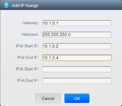
Specify the following:
All the fields are mandatory.
Gateway: The gateway for the tier you create. Ensure that the
gateway is within the Super CIDR range that you specified while
creating the VPC, and is not overlapped with the CIDR of any
existing tier within the VPC.
Netmask: The netmask for the tier you create.
For example, if the VPC CIDR is 10.0.0.0/16 and the network tier
CIDR is 10.0.1.0/24, the gateway of the tier is 10.0.1.1, and the
netmask of the tier is 255.255.255.0.
Start IP/ End IP: A range of IP addresses that are accessible
from the Internet and will be allocated to guest VMs. Enter the
first and last IP addresses that define a range that CloudStack
can assign to guest VMs .
Click OK.
Isolation in Advanced Zone Using Private VLAN
Isolation of guest traffic in shared networks can be achieved by using
Private VLANs (PVLAN). PVLANs provide Layer 2 isolation between ports
within the same VLAN. In a PVLAN-enabled shared network, a user VM
cannot reach other user VM though they can reach the DHCP server and
gateway, this would in turn allow users to control traffic within a
network and help them deploy multiple applications without communication
between application as well as prevent communication with other users’
VMs.
- Isolate VMs in a shared networks by using Private VLANs.
- Supported on KVM, XenServer, and VMware hypervisors
- PVLAN-enabled shared network can be a part of multiple networks of a
guest VM.
About Private VLAN
In an Ethernet switch, a VLAN is a broadcast domain where hosts can
establish direct communication with each another at Layer 2. Private
VLAN is designed as an extension of VLAN standard to add further
segmentation of the logical broadcast domain. A regular VLAN is a single
broadcast domain, whereas a private VLAN partitions a larger VLAN
broadcast domain into smaller sub-domains. A sub-domain is represented
by a pair of VLANs: a Primary VLAN and a Secondary VLAN. The original
VLAN that is being divided into smaller groups is called Primary, which
implies that all VLAN pairs in a private VLAN share the same Primary
VLAN. All the secondary VLANs exist only inside the Primary. Each
Secondary VLAN has a specific VLAN ID associated to it, which
differentiates one sub-domain from another.
Three types of ports exist in a private VLAN domain, which essentially
determine the behaviour of the participating hosts. Each ports will have
its own unique set of rules, which regulate a connected host’s ability
to communicate with other connected host within the same private VLAN
domain. Configure each host that is part of a PVLAN pair can be by using
one of these three port designation:
- Promiscuous: A promiscuous port can communicate with all the
interfaces, including the community and isolated host ports that
belong to the secondary VLANs. In Promiscuous mode, hosts are
connected to promiscuous ports and are able to communicate directly
with resources on both primary and secondary VLAN. Routers, DHCP
servers, and other trusted devices are typically attached to
promiscuous ports.
- Isolated VLANs: The ports within an isolated VLAN cannot
communicate with each other at the layer-2 level. The hosts that are
connected to Isolated ports can directly communicate only with the
Promiscuous resources. If your customer device needs to have access
only to a gateway router, attach it to an isolated port.
- Community VLANs: The ports within a community VLAN can
communicate with each other and with the promiscuous ports, but they
cannot communicate with the ports in other communities at the layer-2
level. In a Community mode, direct communication is permitted only
with the hosts in the same community and those that are connected to
the Primary PVLAN in promiscuous mode. If your customer has two
devices that need to be isolated from other customers’ devices, but
to be able to communicate among themselves, deploy them in community
ports.
For further reading:
Prerequisites
Use a PVLAN supported switch.
See Private VLAN Catalyst Switch Support
Matrix for
more information.
All the layer 2 switches, which are PVLAN-aware, are connected to
each other, and one of them is connected to a router. All the ports
connected to the host would be configured in trunk mode. Open
Management VLAN, Primary VLAN (public) and Secondary Isolated VLAN
ports. Configure the switch port connected to the router in PVLAN
promiscuous trunk mode, which would translate an isolated VLAN to
primary VLAN for the PVLAN-unaware router.
Note that only Cisco Catalyst 4500 has the PVLAN promiscuous trunk
mode to connect both normal VLAN and PVLAN to a PVLAN-unaware switch.
For the other Catalyst PVLAN support switch, connect the switch to
upper switch by using cables, one each for a PVLAN pair.
Configure private VLAN on your physical switches out-of-band.
Before you use PVLAN on XenServer and KVM, enable Open vSwitch (OVS).
Note
OVS on XenServer and KVM does not support PVLAN natively. Therefore,
CloudStack managed to simulate PVLAN on OVS for XenServer and KVM by
modifying the flow table.
Creating a PVLAN-Enabled Guest Network
Log in to the CloudStack UI as administrator.
In the left navigation, choose Infrastructure.
On Zones, click View More.
Click the zone to which you want to add a guest network.
Click the Physical Network tab.
Click the physical network you want to work with.
On the Guest node of the diagram, click Configure.
Click the Network tab.
Click Add guest network.
The Add guest network window is displayed.
Specify the following:
Name: The name of the network. This will be visible to the
user.
Description: The short description of the network that can be
displayed to users.
VLAN ID: The unique ID of the VLAN.
Secondary Isolated VLAN ID: The unique ID of the Secondary
Isolated VLAN.
For the description on Secondary Isolated VLAN, see
About Private VLAN”.
Scope: The available scopes are Domain, Account, Project, and
All.
- Domain: Selecting Domain limits the scope of this guest
network to the domain you specify. The network will not be
available for other domains. If you select Subdomain Access,
the guest network is available to all the sub domains within
the selected domain.
- Account: The account for which the guest network is being
created for. You must specify the domain the account belongs
to.
- Project: The project for which the guest network is being
created for. You must specify the domain the project belongs
to.
- All: The guest network is available for all the domains,
account, projects within the selected zone.
Network Offering: If the administrator has configured multiple
network offerings, select the one you want to use for this
network.
Gateway: The gateway that the guests should use.
Netmask: The netmask in use on the subnet the guests will use.
IP Range: A range of IP addresses that are accessible from the
Internet and are assigned to the guest VMs.
Network Domain: A custom DNS suffix at the level of a network.
If you want to assign a special domain name to the guest VM
network, specify a DNS suffix.
Click OK to confirm.
Security Groups
About Security Groups
Security groups provide a way to isolate traffic to VMs. A security
group is a group of VMs that filter their incoming and outgoing traffic
according to a set of rules, called ingress and egress rules. These
rules filter network traffic according to the IP address that is
attempting to communicate with the VM. Security groups are particularly
useful in zones that use basic networking, because there is a single
guest network for all guest VMs. In advanced zones, security groups are
supported only on the KVM hypervisor.
Note
In a zone that uses advanced networking, you can instead define
multiple guest networks to isolate traffic to VMs.
Each CloudStack account comes with a default security group that denies
all inbound traffic and allows all outbound traffic. The default
security group can be modified so that all new VMs inherit some other
desired set of rules.
Any CloudStack user can set up any number of additional security groups.
When a new VM is launched, it is assigned to the default security group
unless another user-defined security group is specified. A VM can be a
member of any number of security groups. Once a VM is assigned to a
security group, it remains in that group for its entire lifetime; you
can not move a running VM from one security group to another.
You can modify a security group by deleting or adding any number of
ingress and egress rules. When you do, the new rules apply to all VMs in
the group, whether running or stopped.
If no ingress rules are specified, then no traffic will be allowed in,
except for responses to any traffic that has been allowed out through an
egress rule.
Adding a Security Group
A user or administrator can define a new security group.
Log in to the CloudStack UI as an administrator or end user.
In the left navigation, choose Network.
In Select view, choose Security Groups.
Click Add Security Group.
Provide a name and description.
Click OK.
The new security group appears in the Security Groups Details tab.
To make the security group useful, continue to Adding Ingress and
Egress Rules to a Security Group.
Security Groups in Advanced Zones (KVM Only)
CloudStack provides the ability to use security groups to provide
isolation between guests on a single shared, zone-wide network in an
advanced zone where KVM is the hypervisor. Using security groups in
advanced zones rather than multiple VLANs allows a greater range of
options for setting up guest isolation in a cloud.
Limitations
The following are not supported for this feature:
- Two IP ranges with the same VLAN and different gateway or netmask in
security group-enabled shared network.
- Two IP ranges with the same VLAN and different gateway or netmask in
account-specific shared networks.
- Multiple VLAN ranges in security group-enabled shared network.
- Multiple VLAN ranges in account-specific shared networks.
Security groups must be enabled in the zone in order for this feature to
be used.
Enabling Security Groups
In order for security groups to function in a zone, the security groups
feature must first be enabled for the zone. The administrator can do
this when creating a new zone, by selecting a network offering that
includes security groups. The procedure is described in Basic Zone
Configuration in the Advanced Installation Guide. The administrator can
not enable security groups for an existing zone, only when creating a
new zone.
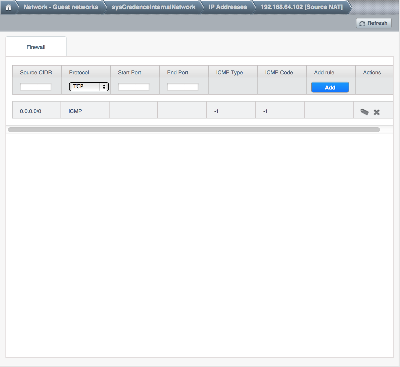
Adding Ingress and Egress Rules to a Security Group
Log in to the CloudStack UI as an administrator or end user.
In the left navigation, choose Network
In Select view, choose Security Groups, then click the security group
you want.
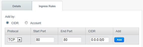
To add an ingress rule, click the Ingress Rules tab and fill out the
following fields to specify what network traffic is allowed into VM
instances in this security group. If no ingress rules are specified,
then no traffic will be allowed in, except for responses to any
traffic that has been allowed out through an egress rule.
- Add by CIDR/Account. Indicate whether the source of the
traffic will be defined by IP address (CIDR) or an existing
security group in a CloudStack account (Account). Choose Account
if you want to allow incoming traffic from all VMs in another
security group
- Protocol. The networking protocol that sources will use to
send traffic to the security group. TCP and UDP are typically used
for data exchange and end-user communications. ICMP is typically
used to send error messages or network monitoring data.
- Start Port, End Port. (TCP, UDP only) A range of listening
ports that are the destination for the incoming traffic. If you
are opening a single port, use the same number in both fields.
- ICMP Type, ICMP Code. (ICMP only) The type of message and
error code that will be accepted.
- CIDR. (Add by CIDR only) To accept only traffic from IP
addresses within a particular address block, enter a CIDR or a
comma-separated list of CIDRs. The CIDR is the base IP address of
the incoming traffic. For example, 192.168.0.0/22. To allow all
CIDRs, set to 0.0.0.0/0.
- Account, Security Group. (Add by Account only) To accept only
traffic from another security group, enter the CloudStack account
and name of a security group that has already been defined in that
account. To allow traffic between VMs within the security group
you are editing now, enter the same name you used in step 7.
The following example allows inbound HTTP access from anywhere:
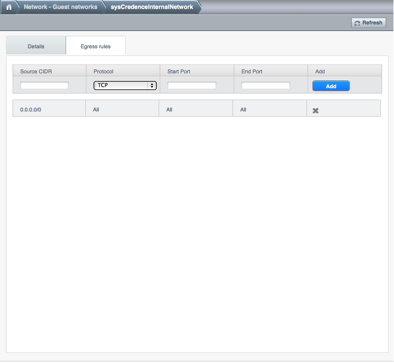
To add an egress rule, click the Egress Rules tab and fill out the
following fields to specify what type of traffic is allowed to be
sent out of VM instances in this security group. If no egress rules
are specified, then all traffic will be allowed out. Once egress
rules are specified, the following types of traffic are allowed out:
traffic specified in egress rules; queries to DNS and DHCP servers;
and responses to any traffic that has been allowed in through an
ingress rule
- Add by CIDR/Account. Indicate whether the destination of the
traffic will be defined by IP address (CIDR) or an existing
security group in a CloudStack account (Account). Choose Account
if you want to allow outgoing traffic to all VMs in another
security group.
- Protocol. The networking protocol that VMs will use to send
outgoing traffic. TCP and UDP are typically used for data exchange
and end-user communications. ICMP is typically used to send error
messages or network monitoring data.
- Start Port, End Port. (TCP, UDP only) A range of listening
ports that are the destination for the outgoing traffic. If you
are opening a single port, use the same number in both fields.
- ICMP Type, ICMP Code. (ICMP only) The type of message and
error code that will be sent
- CIDR. (Add by CIDR only) To send traffic only to IP addresses
within a particular address block, enter a CIDR or a
comma-separated list of CIDRs. The CIDR is the base IP address of
the destination. For example, 192.168.0.0/22. To allow all CIDRs,
set to 0.0.0.0/0.
- Account, Security Group. (Add by Account only) To allow
traffic to be sent to another security group, enter the CloudStack
account and name of a security group that has already been defined
in that account. To allow traffic between VMs within the security
group you are editing now, enter its name.
Click Add.
External Firewalls and Load Balancers
CloudStack is capable of replacing its Virtual Router with an external
Juniper SRX device and an optional external NetScaler or F5 load
balancer for gateway and load balancing services. In this case, the VMs
use the SRX as their gateway.
About Using a NetScaler Load Balancer
Citrix NetScaler is supported as an external network element for load
balancing in zones that use isolated networking in advanced zones. Set
up an external load balancer when you want to provide load balancing
through means other than CloudStack’s provided virtual router.
Note
In a Basic zone, load balancing service is supported only if
Elastic IP or Elastic LB services are enabled.
When NetScaler load balancer is used to provide EIP or ELB services in a
Basic zone, ensure that all guest VM traffic must enter and exit through
the NetScaler device. When inbound traffic goes through the NetScaler
device, traffic is routed by using the NAT protocol depending on the
EIP/ELB configured on the public IP to the private IP. The traffic that
is originated from the guest VMs usually goes through the layer 3
router. To ensure that outbound traffic goes through NetScaler device
providing EIP/ELB, layer 3 router must have a policy-based routing. A
policy-based route must be set up so that all traffic originated from
the guest VM’s are directed to NetScaler device. This is required to
ensure that the outbound traffic from the guest VM’s is routed to a
public IP by using NAT.For more information on Elastic IP, see
“About Elastic IP”.
The NetScaler can be set up in direct (outside the firewall) mode. It
must be added before any load balancing rules are deployed on guest VMs
in the zone.
The functional behavior of the NetScaler with CloudStack is the same as
described in the CloudStack documentation for using an F5 external load
balancer. The only exception is that the F5 supports routing domains,
and NetScaler does not. NetScaler can not yet be used as a firewall.
To install and enable an external load balancer for CloudStack
management, see External Guest Load Balancer Integration in the
Installation Guide.
The Citrix NetScaler comes in three varieties. The following
summarizes how these variants are treated in CloudStack.
MPX
- Physical appliance. Capable of deep packet inspection. Can act as
application firewall and load balancer
- In advanced zones, load balancer functionality fully supported without
limitation. In basic zones, static NAT, elastic IP (EIP), and elastic
load balancing (ELB) are also provided.
VPX
- Virtual appliance. Can run as VM on XenServer, ESXi, and Hyper-V
hypervisors. Same functionality as MPX
- Supported on ESXi and XenServer. Same functional support as for MPX.
CloudStack will treat VPX and MPX as the same device type.
SDX
- Physical appliance. Can create multiple fully isolated VPX instances on
a single appliance to support multi-tenant usage
- CloudStack will dynamically provision, configure, and manage the life
cycle of VPX instances on the SDX. Provisioned instances are added into
CloudStack automatically - no manual configuration by the administrator
is required. Once a VPX instance is added into CloudStack, it is treated
the same as a VPX on an ESXi host.
Initial Setup of External Firewalls and Load Balancers
When the first VM is created for a new account, CloudStack programs the
external firewall and load balancer to work with the VM. The following
objects are created on the firewall:
- A new logical interface to connect to the account’s private VLAN. The
interface IP is always the first IP of the account’s private subnet
(e.g. 10.1.1.1).
- A source NAT rule that forwards all outgoing traffic from the
account’s private VLAN to the public Internet, using the account’s
public IP address as the source address
- A firewall filter counter that measures the number of bytes of
outgoing traffic for the account
The following objects are created on the load balancer:
- A new VLAN that matches the account’s provisioned Zone VLAN
- A self IP for the VLAN. This is always the second IP of the account’s
private subnet (e.g. 10.1.1.2).
Ongoing Configuration of External Firewalls and Load Balancers
Additional user actions (e.g. setting a port forward) will cause further
programming of the firewall and load balancer. A user may request
additional public IP addresses and forward traffic received at these IPs
to specific VMs. This is accomplished by enabling static NAT for a
public IP address, assigning the IP to a VM, and specifying a set of
protocols and port ranges to open. When a static NAT rule is created,
CloudStack programs the zone’s external firewall with the following
objects:
- A static NAT rule that maps the public IP address to the private IP
address of a VM.
- A security policy that allows traffic within the set of protocols and
port ranges that are specified.
- A firewall filter counter that measures the number of bytes of
incoming traffic to the public IP.
The number of incoming and outgoing bytes through source NAT, static
NAT, and load balancing rules is measured and saved on each external
element. This data is collected on a regular basis and stored in the
CloudStack database.
Load Balancer Rules
A CloudStack user or administrator may create load balancing rules that
balance traffic received at a public IP to one or more VMs. A user
creates a rule, specifies an algorithm, and assigns the rule to a set of
VMs.
Note
If you create load balancing rules while using a network service
offering that includes an external load balancer device such as
NetScaler, and later change the network service offering to one that
uses the CloudStack virtual router, you must create a firewall rule on
the virtual router for each of your existing load balancing rules so
that they continue to function.
Adding a Load Balancer Rule
Log in to the CloudStack UI as an administrator or end user.
In the left navigation, choose Network.
Click the name of the network where you want to load balance the
traffic.
Click View IP Addresses.
Click the IP address for which you want to create the rule, then
click the Configuration tab.
In the Load Balancing node of the diagram, click View All.
In a Basic zone, you can also create a load balancing rule without
acquiring or selecting an IP address. CloudStack internally assign an
IP when you create the load balancing rule, which is listed in the IP
Addresses page when the rule is created.
To do that, select the name of the network, then click Add Load
Balancer tab. Continue with #7.
Fill in the following:
- Name: A name for the load balancer rule.
- Public Port: The port receiving incoming traffic to be
balanced.
- Private Port: The port that the VMs will use to receive the
traffic.
- Algorithm: Choose the load balancing algorithm you want
CloudStack to use. CloudStack supports a variety of well-known
algorithms. If you are not familiar with these choices, you will
find plenty of information about them on the Internet.
- Stickiness: (Optional) Click Configure and choose the
algorithm for the stickiness policy. See Sticky Session Policies
for Load Balancer Rules.
- AutoScale: Click Configure and complete the AutoScale
configuration as explained in Configuring AutoScale.
- Health Check: (Optional; NetScaler load balancers only) Click
Configure and fill in the characteristics of the health check
policy. See Health Checks for Load Balancer Rules.
- Ping path (Optional): Sequence of destinations to which to
send health check queries. Default: / (all).
- Response time (Optional): How long to wait for a response
from the health check (2 - 60 seconds). Default: 5 seconds.
- Interval time (Optional): Amount of time between health
checks (1 second - 5 minutes). Default value is set in the
global configuration parameter lbrule_health
check_time_interval.
- Healthy threshold (Optional): Number of consecutive health
check successes that are required before declaring an instance
healthy. Default: 2.
- Unhealthy threshold (Optional): Number of consecutive
health check failures that are required before declaring an
instance unhealthy. Default: 10.
Click Add VMs, then select two or more VMs that will divide the load
of incoming traffic, and click Apply.
The new load balancer rule appears in the list. You can repeat these
steps to add more load balancer rules for this IP address.
Sticky Session Policies for Load Balancer Rules
Sticky sessions are used in Web-based applications to ensure continued
availability of information across the multiple requests in a user’s
session. For example, if a shopper is filling a cart, you need to
remember what has been purchased so far. The concept of “stickiness” is
also referred to as persistence or maintaining state.
Any load balancer rule defined in CloudStack can have a stickiness
policy. The policy consists of a name, stickiness method, and
parameters. The parameters are name-value pairs or flags, which are
defined by the load balancer vendor. The stickiness method could be load
balancer-generated cookie, application-generated cookie, or
source-based. In the source-based method, the source IP address is used
to identify the user and locate the user’s stored data. In the other
methods, cookies are used. The cookie generated by the load balancer or
application is included in request and response URLs to create
persistence. The cookie name can be specified by the administrator or
automatically generated. A variety of options are provided to control
the exact behavior of cookies, such as how they are generated and
whether they are cached.
For the most up to date list of available stickiness methods, see the
CloudStack UI or call listNetworks and check the
SupportedStickinessMethods capability.
Health Checks for Load Balancer Rules
(NetScaler load balancer only; requires NetScaler version 10.0)
Health checks are used in load-balanced applications to ensure that
requests are forwarded only to running, available services. When
creating a load balancer rule, you can specify a health check policy.
This is in addition to specifying the stickiness policy, algorithm, and
other load balancer rule options. You can configure one health check
policy per load balancer rule.
Any load balancer rule defined on a NetScaler load balancer in
CloudStack can have a health check policy. The policy consists of a ping
path, thresholds to define “healthy” and “unhealthy” states, health
check frequency, and timeout wait interval.
When a health check policy is in effect, the load balancer will stop
forwarding requests to any resources that are found to be unhealthy. If
the resource later becomes available again, the periodic health check
will discover it, and the resource will once again be added to the pool
of resources that can receive requests from the load balancer. At any
given time, the most recent result of the health check is displayed in
the UI. For any VM that is attached to a load balancer rule with a
health check configured, the state will be shown as UP or DOWN in the UI
depending on the result of the most recent health check.
You can delete or modify existing health check policies.
To configure how often the health check is performed by default, use the
global configuration setting healthcheck.update.interval (default value
is 600 seconds). You can override this value for an individual health
check policy.
For details on how to set a health check policy using the UI, see
Adding a Load Balancer Rule.
Configuring AutoScale
AutoScaling allows you to scale your back-end services or application
VMs up or down seamlessly and automatically according to the conditions
you define. With AutoScaling enabled, you can ensure that the number of
VMs you are using seamlessly scale up when demand increases, and
automatically decreases when demand subsides. Thus it helps you save
compute costs by terminating underused VMs automatically and launching
new VMs when you need them, without the need for manual intervention.
NetScaler AutoScaling is designed to seamlessly launch or terminate VMs
based on user-defined conditions. Conditions for triggering a scaleup or
scaledown action can vary from a simple use case like monitoring the CPU
usage of a server to a complex use case of monitoring a combination of
server’s responsiveness and its CPU usage. For example, you can
configure AutoScaling to launch an additional VM whenever CPU usage
exceeds 80 percent for 15 minutes, or to remove a VM whenever CPU usage
is less than 20 percent for 30 minutes.
CloudStack uses the NetScaler load balancer to monitor all aspects of a
system’s health and work in unison with CloudStack to initiate scale-up
or scale-down actions.
Note
AutoScale is supported on NetScaler Release 10 Build 74.4006.e and beyond.
Prerequisites
Before you configure an AutoScale rule, consider the following:
Ensure that the necessary template is prepared before configuring
AutoScale. When a VM is deployed by using a template and when it
comes up, the application should be up and running.
Note
If the application is not running, the NetScaler device considers the
VM as ineffective and continues provisioning the VMs unconditionally
until the resource limit is exhausted.
Deploy the templates you prepared. Ensure that the applications come
up on the first boot and is ready to take the traffic. Observe the
time requires to deploy the template. Consider this time when you
specify the quiet time while configuring AutoScale.
The AutoScale feature supports the SNMP counters that can be used to
define conditions for taking scale up or scale down actions. To
monitor the SNMP-based counter, ensure that the SNMP agent is
installed in the template used for creating the AutoScale VMs, and
the SNMP operations work with the configured SNMP community and port
by using standard SNMP managers. For example, see
“Configuring SNMP Community String on a RHELServer”
to configure SNMP on a RHEL machine.
Ensure that the endpointe.url parameter present in the Global
Settings is set to the Management Server API URL. For example,
http://10.102.102.22:8080/client/api. In a multi-node Management
Server deployment, use the virtual IP address configured in the load
balancer for the management server’s cluster. Additionally, ensure
that the NetScaler device has access to this IP address to provide
AutoScale support.
If you update the endpointe.url, disable the AutoScale functionality
of the load balancer rules in the system, then enable them back to
reflect the changes. For more information see Updating an AutoScale Configuration.
If the API Key and Secret Key are regenerated for an AutoScale user,
ensure that the AutoScale functionality of the load balancers that
the user participates in are disabled and then enabled to reflect the
configuration changes in the NetScaler.
In an advanced Zone, ensure that at least one VM should be present
before configuring a load balancer rule with AutoScale. Having one VM
in the network ensures that the network is in implemented state for
configuring AutoScale.
Configuration
Specify the following:
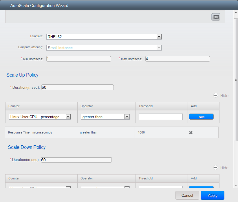
Template: A template consists of a base OS image and application.
A template is used to provision the new instance of an application on
a scaleup action. When a VM is deployed from a template, the VM can
start taking the traffic from the load balancer without any admin
intervention. For example, if the VM is deployed for a Web service,
it should have the Web server running, the database connected, and so
on.
Compute offering: A predefined set of virtual hardware
attributes, including CPU speed, number of CPUs, and RAM size, that
the user can select when creating a new virtual machine instance.
Choose one of the compute offerings to be used while provisioning a
VM instance as part of scaleup action.
Min Instance: The minimum number of active VM instances that is
assigned to a load balancing rule. The active VM instances are the
application instances that are up and serving the traffic, and are
being load balanced. This parameter ensures that a load balancing
rule has at least the configured number of active VM instances are
available to serve the traffic.
Note
If an application, such as SAP, running on a VM instance is down for
some reason, the VM is then not counted as part of Min Instance
parameter, and the AutoScale feature initiates a scaleup action if
the number of active VM instances is below the configured value.
Similarly, when an application instance comes up from its earlier
down state, this application instance is counted as part of the
active instance count and the AutoScale process initiates a scaledown
action when the active instance count breaches the Max instance
value.
Max Instance: Maximum number of active VM instances that should
be assigned toa load balancing rule. This parameter defines the
upper limit of active VM instances that can be assigned to a load
balancing rule.
Specifying a large value for the maximum instance parameter might
result in provisioning large number of VM instances, which in turn
leads to a single load balancing rule exhausting the VM instances
limit specified at the account or domain level.
Note
If an application, such as SAP, running on a VM instance is down for
some reason, the VM is not counted as part of Max Instance parameter.
So there may be scenarios where the number of VMs provisioned for a
scaleup action might be more than the configured Max Instance value.
Once the application instances in the VMs are up from an earlier down
state, the AutoScale feature starts aligning to the configured Max
Instance value.
Specify the following scale-up and scale-down policies:
- Duration: The duration, in seconds, for which the conditions you
specify must be true to trigger a scaleup action. The conditions
defined should hold true for the entire duration you specify for an
AutoScale action to be invoked.
- Counter: The performance counters expose the state of the
monitored instances. By default, CloudStack offers four performance
counters: Three SNMP counters and one NetScaler counter. The SNMP
counters are Linux User CPU, Linux System CPU, and Linux CPU Idle.
The NetScaler counter is ResponseTime. The root administrator can add
additional counters into CloudStack by using the CloudStack API.
- Operator: The following five relational operators are supported
in AutoScale feature: Greater than, Less than, Less than or equal to,
Greater than or equal to, and Equal to.
- Threshold: Threshold value to be used for the counter. Once the
counter defined above breaches the threshold value, the AutoScale
feature initiates a scaleup or scaledown action.
- Add: Click Add to add the condition.
Additionally, if you want to configure the advanced settings, click Show
advanced settings, and specify the following:
- Polling interval: Frequency in which the conditions, combination
of counter, operator and threshold, are to be evaluated before taking
a scale up or down action. The default polling interval is 30
seconds.
- Quiet Time: This is the cool down period after an AutoScale
action is initiated. The time includes the time taken to complete
provisioning a VM instance from its template and the time taken by an
application to be ready to serve traffic. This quiet time allows the
fleet to come up to a stable state before any action can take place.
The default is 300 seconds.
- Destroy VM Grace Period: The duration in seconds, after a
scaledown action is initiated, to wait before the VM is destroyed as
part of scaledown action. This is to ensure graceful close of any
pending sessions or transactions being served by the VM marked for
destroy. The default is 120 seconds.
- Security Groups: Security groups provide a way to isolate traffic
to the VM instances. A security group is a group of VMs that filter
their incoming and outgoing traffic according to a set of rules,
called ingress and egress rules. These rules filter network traffic
according to the IP address that is attempting to communicate with
the VM.
- Disk Offerings: A predefined set of disk size for primary data
storage.
- SNMP Community: The SNMP community string to be used by the
NetScaler device to query the configured counter value from the
provisioned VM instances. Default is public.
- SNMP Port: The port number on which the SNMP agent that run on
the provisioned VMs is listening. Default port is 161.
- User: This is the user that the NetScaler device use to invoke
scaleup and scaledown API calls to the cloud. If no option is
specified, the user who configures AutoScaling is applied. Specify
another user name to override.
- Apply: Click Apply to create the AutoScale configuration.
Disabling and Enabling an AutoScale Configuration
If you want to perform any maintenance operation on the AutoScale VM
instances, disable the AutoScale configuration. When the AutoScale
configuration is disabled, no scaleup or scaledown action is performed.
You can use this downtime for the maintenance activities. To disable the
AutoScale configuration, click the Disable AutoScale  button.
The button toggles between enable and disable, depending on whether
AutoScale is currently enabled or not. After the maintenance operations
are done, you can enable the AutoScale configuration back. To enable,
open the AutoScale configuration page again, then click the Enable
AutoScale button.
Updating an AutoScale Configuration
You can update the various parameters and add or delete the conditions
in a scaleup or scaledown rule. Before you update an AutoScale
configuration, ensure that you disable the AutoScale load balancer rule
by clicking the Disable AutoScale button.
After you modify the required AutoScale parameters, click Apply. To
apply the new AutoScale policies, open the AutoScale configuration page
again, then click the Enable AutoScale button.
Runtime Considerations
- An administrator should not assign a VM to a load balancing rule
which is configured for AutoScale.
- Before a VM provisioning is completed if NetScaler is shutdown or
restarted, the provisioned VM cannot be a part of the load balancing
rule though the intent was to assign it to a load balancing rule. To
workaround, rename the AutoScale provisioned VMs based on the rule
name or ID so at any point of time the VMs can be reconciled to its
load balancing rule.
- Making API calls outside the context of AutoScale, such as destroyVM,
on an autoscaled VM leaves the load balancing configuration in an
inconsistent state. Though VM is destroyed from the load balancer
rule, NetScaler continues to show the VM as a service assigned to a
rule.
Global Server Load Balancing Support
CloudStack supports Global Server Load Balancing (GSLB) functionalities
to provide business continuity, and enable seamless resource movement
within a CloudStack environment. CloudStack achieve this by extending
its functionality of integrating with NetScaler Application Delivery
Controller (ADC), which also provides various GSLB capabilities, such as
disaster recovery and load balancing. The DNS redirection technique is
used to achieve GSLB in CloudStack.
In order to support this functionality, region level services and
service provider are introduced. A new service ‘GSLB’ is introduced as a
region level service. The GSLB service provider is introduced that will
provider the GSLB service. Currently, NetScaler is the supported GSLB
provider in CloudStack. GSLB functionality works in an Active-Active
data center environment.
About Global Server Load Balancing
Global Server Load Balancing (GSLB) is an extension of load balancing
functionality, which is highly efficient in avoiding downtime. Based on
the nature of deployment, GSLB represents a set of technologies that is
used for various purposes, such as load sharing, disaster recovery,
performance, and legal obligations. With GSLB, workloads can be
distributed across multiple data centers situated at geographically
separated locations. GSLB can also provide an alternate location for
accessing a resource in the event of a failure, or to provide a means of
shifting traffic easily to simplify maintenance, or both.
Components of GSLB
A typical GSLB environment is comprised of the following components:
- GSLB Site: In CloudStack terminology, GSLB sites are represented
by zones that are mapped to data centers, each of which has various
network appliances. Each GSLB site is managed by a NetScaler
appliance that is local to that site. Each of these appliances treats
its own site as the local site and all other sites, managed by other
appliances, as remote sites. It is the central entity in a GSLB
deployment, and is represented by a name and an IP address.
- GSLB Services: A GSLB service is typically represented by a load
balancing or content switching virtual server. In a GSLB environment,
you can have a local as well as remote GSLB services. A local GSLB
service represents a local load balancing or content switching
virtual server. A remote GSLB service is the one configured at one of
the other sites in the GSLB setup. At each site in the GSLB setup,
you can create one local GSLB service and any number of remote GSLB
services.
- GSLB Virtual Servers: A GSLB virtual server refers to one or more
GSLB services and balances traffic between traffic across the VMs in
multiple zones by using the CloudStack functionality. It evaluates
the configured GSLB methods or algorithms to select a GSLB service to
which to send the client requests. One or more virtual servers from
different zones are bound to the GSLB virtual server. GSLB virtual
server does not have a public IP associated with it, instead it will
have a FQDN DNS name.
- Load Balancing or Content Switching Virtual Servers: According to
Citrix NetScaler terminology, a load balancing or content switching
virtual server represents one or many servers on the local network.
Clients send their requests to the load balancing or content
switching virtual server’s virtual IP (VIP) address, and the virtual
server balances the load across the local servers. After a GSLB
virtual server selects a GSLB service representing either a local or
a remote load balancing or content switching virtual server, the
client sends the request to that virtual server’s VIP address.
- DNS VIPs: DNS virtual IP represents a load balancing DNS virtual
server on the GSLB service provider. The DNS requests for domains for
which the GSLB service provider is authoritative can be sent to a DNS
VIP.
- Authoritative DNS: ADNS (Authoritative Domain Name Server) is a
service that provides actual answer to DNS queries, such as web site
IP address. In a GSLB environment, an ADNS service responds only to
DNS requests for domains for which the GSLB service provider is
authoritative. When an ADNS service is configured, the service
provider owns that IP address and advertises it. When you create an
ADNS service, the NetScaler responds to DNS queries on the configured
ADNS service IP and port.
How Does GSLB Works in CloudStack?
Global server load balancing is used to manage the traffic flow to a web
site hosted on two separate zones that ideally are in different
geographic locations. The following is an illustration of how GLSB
functionality is provided in CloudStack: An organization, xyztelco, has
set up a public cloud that spans two zones, Zone-1 and Zone-2, across
geographically separated data centers that are managed by CloudStack.
Tenant-A of the cloud launches a highly available solution by using
xyztelco cloud. For that purpose, they launch two instances each in both
the zones: VM1 and VM2 in Zone-1 and VM5 and VM6 in Zone-2. Tenant-A
acquires a public IP, IP-1 in Zone-1, and configures a load balancer
rule to load balance the traffic between VM1 and VM2 instances.
CloudStack orchestrates setting up a virtual server on the LB service
provider in Zone-1. Virtual server 1 that is set up on the LB service
provider in Zone-1 represents a publicly accessible virtual server that
client reaches at IP-1. The client traffic to virtual server 1 at IP-1
will be load balanced across VM1 and VM2 instances.
Tenant-A acquires another public IP, IP-2 in Zone-2 and sets up a load
balancer rule to load balance the traffic between VM5 and VM6 instances.
Similarly in Zone-2, CloudStack orchestrates setting up a virtual server
on the LB service provider. Virtual server 2 that is setup on the LB
service provider in Zone-2 represents a publicly accessible virtual
server that client reaches at IP-2. The client traffic that reaches
virtual server 2 at IP-2 is load balanced across VM5 and VM6 instances.
At this point Tenant-A has the service enabled in both the zones, but
has no means to set up a disaster recovery plan if one of the zone
fails. Additionally, there is no way for Tenant-A to load balance the
traffic intelligently to one of the zones based on load, proximity and
so on. The cloud administrator of xyztelco provisions a GSLB service
provider to both the zones. A GSLB provider is typically an ADC that has
the ability to act as an ADNS (Authoritative Domain Name Server) and has
the mechanism to monitor health of virtual servers both at local and
remote sites. The cloud admin enables GSLB as a service to the tenants
that use zones 1 and 2.
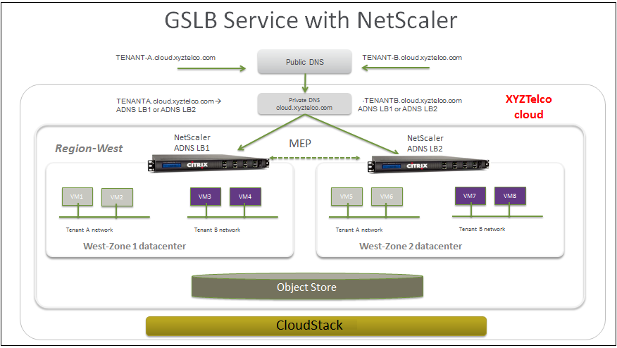
Tenant-A wishes to leverage the GSLB service provided by the xyztelco
cloud. Tenant-A configures a GSLB rule to load balance traffic across
virtual server 1 at Zone-1 and virtual server 2 at Zone-2. The domain
name is provided as A.xyztelco.com. CloudStack orchestrates setting up
GSLB virtual server 1 on the GSLB service provider at Zone-1. CloudStack
binds virtual server 1 of Zone-1 and virtual server 2 of Zone-2 to GLSB
virtual server 1. GSLB virtual server 1 is configured to start
monitoring the health of virtual server 1 and 2 in Zone-1. CloudStack
will also orchestrate setting up GSLB virtual server 2 on GSLB service
provider at Zone-2. CloudStack will bind virtual server 1 of Zone-1 and
virtual server 2 of Zone-2 to GLSB virtual server 2. GSLB virtual server
2 is configured to start monitoring the health of virtual server 1 and
2. CloudStack will bind the domain A.xyztelco.com to both the GSLB
virtual server 1 and 2. At this point, Tenant-A service will be globally
reachable at A.xyztelco.com. The private DNS server for the domain
xyztelcom.com is configured by the admin out-of-band to resolve the
domain A.xyztelco.com to the GSLB providers at both the zones, which are
configured as ADNS for the domain A.xyztelco.com. A client when sends a
DNS request to resolve A.xyztelcom.com, will eventually get DNS
delegation to the address of GSLB providers at zone 1 and 2. A client
DNS request will be received by the GSLB provider. The GSLB provider,
depending on the domain for which it needs to resolve, will pick up the
GSLB virtual server associated with the domain. Depending on the health
of the virtual servers being load balanced, DNS request for the domain
will be resolved to the public IP associated with the selected virtual
server.
Configuring GSLB
To configure a GSLB deployment, you must first configure a standard load
balancing setup for each zone. This enables you to balance load across
the different servers in each zone in the region. Then on the NetScaler
side, configure both NetScaler appliances that you plan to add to each
zone as authoritative DNS (ADNS) servers. Next, create a GSLB site for
each zone, configure GSLB virtual servers for each site, create GLSB
services, and bind the GSLB services to the GSLB virtual servers.
Finally, bind the domain to the GSLB virtual servers. The GSLB
configurations on the two appliances at the two different zones are
identical, although each sites load-balancing configuration is specific
to that site.
Perform the following as a cloud administrator. As per the example given
above, the administrator of xyztelco is the one who sets up GSLB:
In the cloud.dns.name global parameter, specify the DNS name of your
tenant’s cloud that make use of the GSLB service.
On the NetScaler side, configure GSLB as given in Configuring Global
Server Load Balancing (GSLB):
Configuring a standard load balancing setup.
Configure Authoritative DNS, as explained in Configuring an
Authoritative DNS Service.
Configure a GSLB site with site name formed from the domain name
details.
Configure a GSLB site with the site name formed from the domain
name.
As per the example given above, the site names are A.xyztelco.com
and B.xyztelco.com.
For more information, see Configuring a Basic GSLB Site.
Configure a GSLB virtual server.
For more information, see Configuring a GSLB Virtual Server.
Configure a GSLB service for each virtual server.
For more information, see Configuring a GSLB Service.
Bind the GSLB services to the GSLB virtual server.
For more information, see Binding GSLB Services to a GSLB Virtual
Server.
Bind domain name to GSLB virtual server. Domain name is obtained
from the domain details.
For more information, see Binding a Domain to a GSLB Virtual
Server.
In each zone that are participating in GSLB, add GSLB-enabled
NetScaler device.
For more information, see Enabling GSLB in NetScaler.
As a domain administrator/ user perform the following:
Add a GSLB rule on both the sites.
See “Adding a GSLB Rule”.
Assign load balancer rules.
See “Assigning Load Balancing Rules to GSLB”.
Prerequisites and Guidelines
The GSLB functionality is supported both Basic and Advanced zones.
GSLB is added as a new network service.
GSLB service provider can be added to a physical network in a zone.
The admin is allowed to enable or disable GSLB functionality at
region level.
The admin is allowed to configure a zone as GSLB capable or enabled.
A zone shall be considered as GSLB capable only if a GSLB service
provider is provisioned in the zone.
When users have VMs deployed in multiple availability zones which are
GSLB enabled, they can use the GSLB functionality to load balance
traffic across the VMs in multiple zones.
The users can use GSLB to load balance across the VMs across zones in
a region only if the admin has enabled GSLB in that region.
The users can load balance traffic across the availability zones in
the same region or different regions.
The admin can configure DNS name for the entire cloud.
The users can specify an unique name across the cloud for a globally
load balanced service. The provided name is used as the domain name
under the DNS name associated with the cloud.
The user-provided name along with the admin-provided DNS name is used
to produce a globally resolvable FQDN for the globally load balanced
service of the user. For example, if the admin has configured
xyztelco.com as the DNS name for the cloud, and user specifies ‘foo’
for the GSLB virtual service, then the FQDN name of the GSLB virtual
service is foo.xyztelco.com.
While setting up GSLB, users can select a load balancing method, such
as round robin, for using across the zones that are part of GSLB.
The user shall be able to set weight to zone-level virtual server.
Weight shall be considered by the load balancing method for
distributing the traffic.
The GSLB functionality shall support session persistence, where
series of client requests for particular domain name is sent to a
virtual server on the same zone.
Statistics is collected from each GSLB virtual server.
Enabling GSLB in NetScaler
In each zone, add GSLB-enabled NetScaler device for load balancing.
Log in as administrator to the CloudStack UI.
In the left navigation bar, click Infrastructure.
In Zones, click View More.
Choose the zone you want to work with.
Click the Physical Network tab, then click the name of the physical
network.
In the Network Service Providers node of the diagram, click
Configure.
You might have to scroll down to see this.
Click NetScaler.
Click Add NetScaler device and provide the following:
For NetScaler:
- IP Address: The IP address of the SDX.
- Username/Password: The authentication credentials to access
the device. CloudStack uses these credentials to access the
device.
- Type: The type of device that is being added. It could be F5
Big Ip Load Balancer, NetScaler VPX, NetScaler MPX, or NetScaler
SDX. For a comparison of the NetScaler types, see the CloudStack
Administration Guide.
- Public interface: Interface of device that is configured to be
part of the public network.
- Private interface: Interface of device that is configured to
be part of the private network.
- GSLB service: Select this option.
- GSLB service Public IP: The public IP address of the NAT
translator for a GSLB service that is on a private network.
- GSLB service Private IP: The private IP of the GSLB service.
- Number of Retries. Number of times to attempt a command on the
device before considering the operation failed. Default is 2.
- Capacity: The number of networks the device can handle.
- Dedicated: When marked as dedicated, this device will be
dedicated to a single account. When Dedicated is checked, the
value in the Capacity field has no significance implicitly, its
value is 1.
Click OK.
Adding a GSLB Rule
Log in to the CloudStack UI as a domain administrator or user.
In the left navigation pane, click Region.
Select the region for which you want to create a GSLB rule.
In the Details tab, click View GSLB.
Click Add GSLB.
The Add GSLB page is displayed as follows:
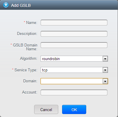
Specify the following:
- Name: Name for the GSLB rule.
- Description: (Optional) A short description of the GSLB rule
that can be displayed to users.
- GSLB Domain Name: A preferred domain name for the service.
- Algorithm: (Optional) The algorithm to use to load balance the
traffic across the zones. The options are Round Robin, Least
Connection, and Proximity.
- Service Type: The transport protocol to use for GSLB. The
options are TCP and UDP.
- Domain: (Optional) The domain for which you want to create the
GSLB rule.
- Account: (Optional) The account on which you want to apply the
GSLB rule.
Click OK to confirm.
Assigning Load Balancing Rules to GSLB
- Log in to the CloudStack UI as a domain administrator or user.
- In the left navigation pane, click Region.
- Select the region for which you want to create a GSLB rule.
- In the Details tab, click View GSLB.
- Select the desired GSLB.
- Click view assigned load balancing.
- Click assign more load balancing.
- Select the load balancing rule you have created for the zone.
- Click OK to confirm.
Known Limitation
Currently, CloudStack does not support orchestration of services across
the zones. The notion of services and service providers in region are to
be introduced.
Guest IP Ranges
The IP ranges for guest network traffic are set on a per-account basis
by the user. This allows the users to configure their network in a
fashion that will enable VPN linking between their guest network and
their clients.
In shared networks in Basic zone and Security Group-enabled Advanced
networks, you will have the flexibility to add multiple guest IP ranges
from different subnets. You can add or remove one IP range at a time.
For more information, see “About Multiple IP
Ranges”.
Acquiring a New IP Address
Log in to the CloudStack UI as an administrator or end user.
In the left navigation, choose Network.
Click the name of the network where you want to work with.
Click View IP Addresses.
Click Acquire New IP.
The Acquire New IP window is displayed.
Specify whether you want cross-zone IP or not.
If you want Portable IP click Yes in the confirmation dialog. If you
want a normal Public IP click No.
For more information on Portable IP, see “Portable
IPs”.
Within a few moments, the new IP address should appear with the state
Allocated. You can now use the IP address in port forwarding or
static NAT rules.
Releasing an IP Address
When the last rule for an IP address is removed, you can release that IP
address. The IP address still belongs to the VPC; however, it can be
picked up for any guest network again.
- Log in to the CloudStack UI as an administrator or end user.
- In the left navigation, choose Network.
- Click the name of the network where you want to work with.
- Click View IP Addresses.
- Click the IP address you want to release.
- Click the Release IP button.

Static NAT
A static NAT rule maps a public IP address to the private IP address of
a VM in order to allow Internet traffic into the VM. The public IP
address always remains the same, which is why it is called static NAT.
This section tells how to enable or disable static NAT for a particular
IP address.
Enabling or Disabling Static NAT
If port forwarding rules are already in effect for an IP address, you
cannot enable static NAT to that IP.
If a guest VM is part of more than one network, static NAT rules will
function only if they are defined on the default network.
Log in to the CloudStack UI as an administrator or end user.
In the left navigation, choose Network.
Click the name of the network where you want to work with.
Click View IP Addresses.
Click the IP address you want to work with.
Click the Static NAT  button.
The button toggles between Enable and Disable, depending on whether
static NAT is currently enabled for the IP address.
If you are enabling static NAT, a dialog appears where you can choose
the destination VM and click Apply.
IP Forwarding and Firewalling
By default, all incoming traffic to the public IP address is rejected.
All outgoing traffic from the guests is also blocked by default.
To allow outgoing traffic, follow the procedure in Egress Firewall Rules in an Advanced Zone.
To allow incoming traffic, users may set up firewall rules and/or port
forwarding rules. For example, you can use a firewall rule to open a
range of ports on the public IP address, such as 33 through 44. Then use
port forwarding rules to direct traffic from individual ports within
that range to specific ports on user VMs. For example, one port
forwarding rule could route incoming traffic on the public IP’s port 33
to port 100 on one user VM’s private IP.
Firewall Rules
By default, all incoming traffic to the public IP address is rejected by
the firewall. To allow external traffic, you can open firewall ports by
specifying firewall rules. You can optionally specify one or more CIDRs
to filter the source IPs. This is useful when you want to allow only
incoming requests from certain IP addresses.
You cannot use firewall rules to open ports for an elastic IP address.
When elastic IP is used, outside access is instead controlled through
the use of security groups. See “Adding a Security
Group”.
In an advanced zone, you can also create egress firewall rules by using
the virtual router. For more information, see “Egress Firewall Rules in an Advanced Zone”.
Firewall rules can be created using the Firewall tab in the Management
Server UI. This tab is not displayed by default when CloudStack is
installed. To display the Firewall tab, the CloudStack administrator
must set the global configuration parameter firewall.rule.ui.enabled to
“true.”
To create a firewall rule:
- Log in to the CloudStack UI as an administrator or end user.
- In the left navigation, choose Network.
- Click the name of the network where you want to work with.
- Click View IP Addresses.
- Click the IP address you want to work with.
- Click the Configuration tab and fill in the following values.
- Source CIDR: (Optional) To accept only traffic from IP
addresses within a particular address block, enter a CIDR or a
comma-separated list of CIDRs. Example: 192.168.0.0/22. Leave
empty to allow all CIDRs.
- Protocol: The communication protocol in use on the opened
port(s).
- Start Port and End Port: The port(s) you want to open on the
firewall. If you are opening a single port, use the same number in
both fields
- ICMP Type and ICMP Code: Used only if Protocol is set to ICMP.
Provide the type and code required by the ICMP protocol to fill
out the ICMP header. Refer to ICMP documentation for more details
if you are not sure what to enter
- Click Add.
Egress Firewall Rules in an Advanced Zone
The egress traffic originates from a private network to a public
network, such as the Internet. By default, the egress traffic is blocked
in default network offerings, so no outgoing traffic is allowed from a
guest network to the Internet. However, you can control the egress
traffic in an Advanced zone by creating egress firewall rules. When an
egress firewall rule is applied, the traffic specific to the rule is
allowed and the remaining traffic is blocked. When all the firewall
rules are removed the default policy, Block, is applied.
Prerequisites and Guidelines
Consider the following scenarios to apply egress firewall rules:
- Egress firewall rules are supported on Juniper SRX and virtual
router.
- The egress firewall rules are not supported on shared networks.
- Allow the egress traffic from specified source CIDR. The Source CIDR
is part of guest network CIDR.
- Allow the egress traffic with protocol TCP,UDP,ICMP, or ALL.
- Allow the egress traffic with protocol and destination port range.
The port range is specified for TCP, UDP or for ICMP type and code.
- The default policy is Allow for the new network offerings, whereas on
upgrade existing network offerings with firewall service providers
will have the default egress policy Deny.
Configuring an Egress Firewall Rule
Log in to the CloudStack UI as an administrator or end user.
In the left navigation, choose Network.
In Select view, choose Guest networks, then click the Guest network
you want.
To add an egress rule, click the Egress rules tab and fill out the
following fields to specify what type of traffic is allowed to be
sent out of VM instances in this guest network:
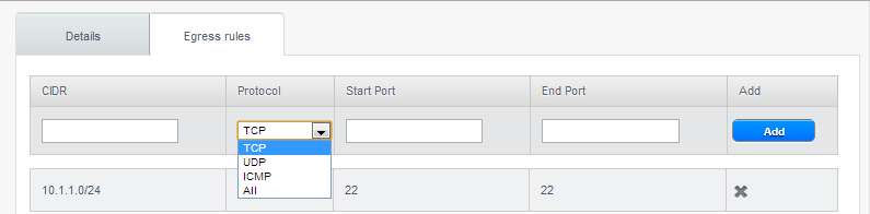
- CIDR: (Add by CIDR only) To send traffic only to the IP
addresses within a particular address block, enter a CIDR or a
comma-separated list of CIDRs. The CIDR is the base IP address of
the destination. For example, 192.168.0.0/22. To allow all CIDRs,
set to 0.0.0.0/0.
- Protocol: The networking protocol that VMs uses to send
outgoing traffic. The TCP and UDP protocols are typically used for
data exchange and end-user communications. The ICMP protocol is
typically used to send error messages or network monitoring data.
- Start Port, End Port: (TCP, UDP only) A range of listening
ports that are the destination for the outgoing traffic. If you
are opening a single port, use the same number in both fields.
- ICMP Type, ICMP Code: (ICMP only) The type of message and
error code that are sent.
Click Add.
Configuring the Default Egress Policy
The default egress policy for Isolated guest network is configured by
using Network offering. Use the create network offering option to
determine whether the default policy should be block or allow all the
traffic to the public network from a guest network. Use this network
offering to create the network. If no policy is specified, by default
all the traffic is allowed from the guest network that you create by
using this network offering.
You have two options: Allow and Deny.
Allow
If you select Allow for a network offering, by default egress traffic is
allowed. However, when an egress rule is configured for a guest network,
rules are applied to block the specified traffic and rest are allowed.
If no egress rules are configured for the network, egress traffic is
accepted.
Deny
If you select Deny for a network offering, by default egress traffic for
the guest network is blocked. However, when an egress rules is
configured for a guest network, rules are applied to allow the specified
traffic. While implementing a guest network, CloudStack adds the
firewall egress rule specific to the default egress policy for the guest
network.
This feature is supported only on virtual router and Juniper SRX.
Create a network offering with your desirable default egress policy:
- Log in with admin privileges to the CloudStack UI.
- In the left navigation bar, click Service Offerings.
- In Select Offering, choose Network Offering.
- Click Add Network Offering.
- In the dialog, make necessary choices, including firewall
provider.
- In the Default egress policy field, specify the behaviour.
- Click OK.
Create an isolated network by using this network offering.
Based on your selection, the network will have the egress public
traffic blocked or allowed.
Port Forwarding
A port forward service is a set of port forwarding rules that define a
policy. A port forward service is then applied to one or more guest VMs.
The guest VM then has its inbound network access managed according to
the policy defined by the port forwarding service. You can optionally
specify one or more CIDRs to filter the source IPs. This is useful when
you want to allow only incoming requests from certain IP addresses to be
forwarded.
A guest VM can be in any number of port forward services. Port forward
services can be defined but have no members. If a guest VM is part of
more than one network, port forwarding rules will function only if they
are defined on the default network
You cannot use port forwarding to open ports for an elastic IP address.
When elastic IP is used, outside access is instead controlled through
the use of security groups. See Security Groups.
To set up port forwarding:
- Log in to the CloudStack UI as an administrator or end user.
- If you have not already done so, add a public IP address range to a
zone in CloudStack. See Adding a Zone and Pod in the Installation
Guide.
- Add one or more VM instances to CloudStack.
- In the left navigation bar, click Network.
- Click the name of the guest network where the VMs are running.
- Choose an existing IP address or acquire a new IP address. See
“Acquiring a New IP Address”.
Click the name of the IP address in the list.
- Click the Configuration tab.
- In the Port Forwarding node of the diagram, click View All.
- Fill in the following:
- Public Port: The port to which public traffic will be
addressed on the IP address you acquired in the previous step.
- Private Port: The port on which the instance is listening for
forwarded public traffic.
- Protocol: The communication protocol in use between the two
ports
- Click Add.
IP Load Balancing
The user may choose to associate the same public IP for multiple guests.
CloudStack implements a TCP-level load balancer with the following
policies.
- Round-robin
- Least connection
- Source IP
This is similar to port forwarding but the destination may be multiple
IP addresses.
DNS and DHCP
The Virtual Router provides DNS and DHCP services to the guests. It
proxies DNS requests to the DNS server configured on the Availability
Zone.
Remote Access VPN
CloudStack account owners can create virtual private networks (VPN) to
access their virtual machines. If the guest network is instantiated from
a network offering that offers the Remote Access VPN service, the
virtual router (based on the System VM) is used to provide the service.
CloudStack provides a L2TP-over-IPsec-based remote access VPN service to
guest virtual networks. Since each network gets its own virtual router,
VPNs are not shared across the networks. VPN clients native to Windows,
Mac OS X and iOS can be used to connect to the guest networks. The
account owner can create and manage users for their VPN. CloudStack does
not use its account database for this purpose but uses a separate table.
The VPN user database is shared across all the VPNs created by the
account owner. All VPN users get access to all VPNs created by the
account owner.
Note
Make sure that not all traffic goes through the VPN. That is, the route
installed by the VPN should be only for the guest network and not for
all traffic.
- Road Warrior / Remote Access. Users want to be able to connect
securely from a home or office to a private network in the cloud.
Typically, the IP address of the connecting client is dynamic and
cannot be preconfigured on the VPN server.
- Site to Site. In this scenario, two private subnets are connected
over the public Internet with a secure VPN tunnel. The cloud user’s
subnet (for example, an office network) is connected through a
gateway to the network in the cloud. The address of the user’s
gateway must be preconfigured on the VPN server in the cloud. Note
that although L2TP-over-IPsec can be used to set up Site-to-Site
VPNs, this is not the primary intent of this feature. For more
information, see “Setting Up a Site-to-Site VPN Connection”.
Configuring Remote Access VPN
To set up VPN for the cloud:
- Log in to the CloudStack UI as an administrator or end user.
- In the left navigation, click Global Settings.
- Set the following global configuration parameters.
- remote.access.vpn.client.ip.range - The range of IP addresses to
be allocated to remote access VPN clients. The first IP in the
range is used by the VPN server.
- remote.access.vpn.psk.length - Length of the IPSec key.
- remote.access.vpn.user.limit - Maximum number of VPN users per
account.
To enable VPN for a particular network:
Log in as a user or administrator to the CloudStack UI.
In the left navigation, click Network.
Click the name of the network you want to work with.
Click View IP Addresses.
Click one of the displayed IP address names.
Click the Enable VPN button. 
The IPsec key is displayed in a popup window.
Configuring Remote Access VPN in VPC
On enabling Remote Access VPN on a VPC, any VPN client present outside
the VPC can access VMs present in the VPC by using the Remote VPN
connection. The VPN client can be present anywhere except inside the VPC
on which the user enabled the Remote Access VPN service.
To enable VPN for a VPC:
Log in as a user or administrator to the CloudStack UI.
In the left navigation, click Network.
In the Select view, select VPC.
All the VPCs that you have created for the account is listed in the
page.
Click the Configure button of the VPC.
For each tier, the following options are displayed:
- Internal LB
- Public LB IP
- Static NAT
- Virtual Machines
- CIDR
The following router information is displayed:
- Private Gateways
- Public IP Addresses
- Site-to-Site VPNs
- Network ACL Lists
In the Router node, select Public IP Addresses.
The IP Addresses page is displayed.
Click Source NAT IP address.
Click the Enable VPN button.
Click OK to confirm. The IPsec key is displayed in a pop-up window.
Now, you need to add the VPN users.
- Click the Source NAT IP.
- Select the VPN tab.
- Add the username and the corresponding password of the user you
wanted to add.
- Click Add.
- Repeat the same steps to add the VPN users.
Using Remote Access VPN with Windows
The procedure to use VPN varies by Windows version. Generally, the user
must edit the VPN properties and make sure that the default route is not
the VPN. The following steps are for Windows L2TP clients on Windows
Vista. The commands should be similar for other Windows versions.
- Log in to the CloudStack UI and click on the source NAT IP for the
account. The VPN tab should display the IPsec preshared key. Make a
note of this and the source NAT IP. The UI also lists one or more
users and their passwords. Choose one of these users, or, if none
exists, add a user and password.
- On the Windows box, go to Control Panel, then select Network and
Sharing center. Click Setup a connection or network.
- In the next dialog, select No, create a new connection.
- In the next dialog, select Use my Internet Connection (VPN).
- In the next dialog, enter the source NAT IP from step
#1 and give the connection a name. Check Don’t
connect now.
- In the next dialog, enter the user name and password selected in step
#1.
- Click Create.
- Go back to the Control Panel and click Network Connections to see the
new connection. The connection is not active yet.
- Right-click the new connection and select Properties. In the
Properties dialog, select the Networking tab.
- In Type of VPN, choose L2TP IPsec VPN, then click IPsec settings.
Select Use preshared key. Enter the preshared key from step #1.
- The connection is ready for activation. Go back to Control Panel ->
Network Connections and double-click the created connection.
- Enter the user name and password from step #1.
Using Remote Access VPN with Mac OS X
First, be sure you’ve configured the VPN settings in your CloudStack
install. This section is only concerned with connecting via Mac OS X to
your VPN.
Note, these instructions were written on Mac OS X 10.7.5. They may
differ slightly in older or newer releases of Mac OS X.
- On your Mac, open System Preferences and click Network.
- Make sure Send all traffic over VPN connection is not checked.
- If your preferences are locked, you’ll need to click the lock in the
bottom left-hand corner to make any changes and provide your
administrator credentials.
- You will need to create a new network entry. Click the plus icon on
the bottom left-hand side and you’ll see a dialog that says “Select
the interface and enter a name for the new service.” Select VPN from
the Interface drop-down menu, and “L2TP over IPSec” for the VPN Type.
Enter whatever you like within the “Service Name” field.
- You’ll now have a new network interface with the name of whatever you
put in the “Service Name” field. For the purposes of this example,
we’ll assume you’ve named it “CloudStack.” Click on that interface
and provide the IP address of the interface for your VPN under the
Server Address field, and the user name for your VPN under Account
Name.
- Click Authentication Settings, and add the user’s password under User
Authentication and enter the pre-shared IPSec key in the Shared
Secret field under Machine Authentication. Click OK.
- You may also want to click the “Show VPN status in menu bar” but
that’s entirely optional.
- Now click “Connect” and you will be connected to the CloudStack VPN.
Setting Up a Site-to-Site VPN Connection
A Site-to-Site VPN connection helps you establish a secure connection
from an enterprise datacenter to the cloud infrastructure. This allows
users to access the guest VMs by establishing a VPN connection to the
virtual router of the account from a device in the datacenter of the
enterprise. You can also establish a secure connection between two VPC
setups or high availability zones in your environment. Having this
facility eliminates the need to establish VPN connections to individual
VMs.
The difference from Remote VPN is that Site-to-site VPNs connects entire
networks to each other, for example, connecting a branch office network
to a company headquarters network. In a site-to-site VPN, hosts do not
have VPN client software; they send and receive normal TCP/IP traffic
through a VPN gateway.
The supported endpoints on the remote datacenters are:
- Cisco ISR with IOS 12.4 or later
- Juniper J-Series routers with JunOS 9.5 or later
- CloudStack virtual routers
Note
In addition to the specific Cisco and Juniper devices listed above, the
expectation is that any Cisco or Juniper device running on the supported
operating systems are able to establish VPN connections.
To set up a Site-to-Site VPN connection, perform the following:
Create a Virtual Private Cloud (VPC).
See “Configuring a Virtual Private Cloud”.
Create a VPN Customer Gateway.
Create a VPN gateway for the VPC that you created.
Create VPN connection from the VPC VPN gateway to the customer VPN
gateway.
Creating and Updating a VPN Customer Gateway
Note
A VPN customer gateway can be connected to only one VPN gateway at a time.
To add a VPN Customer Gateway:
Log in to the CloudStack UI as an administrator or end user.
In the left navigation, choose Network.
In the Select view, select VPN Customer Gateway.
Click Add VPN Customer Gateway.
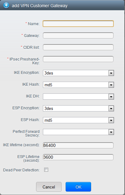
Provide the following information:
Name: A unique name for the VPN customer gateway you create.
Gateway: The IP address for the remote gateway.
CIDR list: The guest CIDR list of the remote subnets. Enter a
CIDR or a comma-separated list of CIDRs. Ensure that a guest CIDR
list is not overlapped with the VPC’s CIDR, or another guest CIDR.
The CIDR must be RFC1918-compliant.
IPsec Preshared Key: Preshared keying is a method where the
endpoints of the VPN share a secret key. This key value is used to
authenticate the customer gateway and the VPC VPN gateway to each
other.
Note
The IKE peers (VPN end points) authenticate each other by
computing and sending a keyed hash of data that includes the
Preshared key. If the receiving peer is able to create the same
hash independently by using its Preshared key, it knows that both
peers must share the same secret, thus authenticating the customer
gateway.
IKE Encryption: The Internet Key Exchange (IKE) policy for
phase-1. The supported encryption algorithms are AES128, AES192,
AES256, and 3DES. Authentication is accomplished through the
Preshared Keys.
Note
The phase-1 is the first phase in the IKE process. In this initial
negotiation phase, the two VPN endpoints agree on the methods to
be used to provide security for the underlying IP traffic. The
phase-1 authenticates the two VPN gateways to each other, by
confirming that the remote gateway has a matching Preshared Key.
IKE Hash: The IKE hash for phase-1. The supported hash
algorithms are SHA1 and MD5.
IKE DH: A public-key cryptography protocol which allows two
parties to establish a shared secret over an insecure
communications channel. The 1536-bit Diffie-Hellman group is used
within IKE to establish session keys. The supported options are
None, Group-5 (1536-bit) and Group-2 (1024-bit).
ESP Encryption: Encapsulating Security Payload (ESP) algorithm
within phase-2. The supported encryption algorithms are AES128,
AES192, AES256, and 3DES.
Note
The phase-2 is the second phase in the IKE process. The purpose of
IKE phase-2 is to negotiate IPSec security associations (SA) to
set up the IPSec tunnel. In phase-2, new keying material is
extracted from the Diffie-Hellman key exchange in phase-1, to
provide session keys to use in protecting the VPN data flow.
ESP Hash: Encapsulating Security Payload (ESP) hash for
phase-2. Supported hash algorithms are SHA1 and MD5.
Perfect Forward Secrecy: Perfect Forward Secrecy (or PFS) is
the property that ensures that a session key derived from a set of
long-term public and private keys will not be compromised. This
property enforces a new Diffie-Hellman key exchange. It provides
the keying material that has greater key material life and thereby
greater resistance to cryptographic attacks. The available options
are None, Group-5 (1536-bit) and Group-2 (1024-bit). The security
of the key exchanges increase as the DH groups grow larger, as
does the time of the exchanges.
Note
When PFS is turned on, for every negotiation of a new phase-2 SA
the two gateways must generate a new set of phase-1 keys. This
adds an extra layer of protection that PFS adds, which ensures if
the phase-2 SA’s have expired, the keys used for new phase-2 SA’s
have not been generated from the current phase-1 keying material.
IKE Lifetime (seconds): The phase-1 lifetime of the security
association in seconds. Default is 86400 seconds (1 day). Whenever
the time expires, a new phase-1 exchange is performed.
ESP Lifetime (seconds): The phase-2 lifetime of the security
association in seconds. Default is 3600 seconds (1 hour). Whenever
the value is exceeded, a re-key is initiated to provide a new
IPsec encryption and authentication session keys.
Dead Peer Detection: A method to detect an unavailable
Internet Key Exchange (IKE) peer. Select this option if you want
the virtual router to query the liveliness of its IKE peer at
regular intervals. It’s recommended to have the same configuration
of DPD on both side of VPN connection.
Click OK.
Updating and Removing a VPN Customer Gateway
You can update a customer gateway either with no VPN connection, or
related VPN connection is in error state.
- Log in to the CloudStack UI as an administrator or end user.
- In the left navigation, choose Network.
- In the Select view, select VPN Customer Gateway.
- Select the VPN customer gateway you want to work with.
- To modify the required parameters, click the Edit VPN Customer
Gateway button
- To remove the VPN customer gateway, click the Delete VPN Customer
Gateway button

- Click OK.
Creating a VPN gateway for the VPC
Log in to the CloudStack UI as an administrator or end user.
In the left navigation, choose Network.
In the Select view, select VPC.
All the VPCs that you have created for the account is listed in the
page.
Click the Configure button of the VPC to which you want to deploy the
VMs.
The VPC page is displayed where all the tiers you created are listed
in a diagram.
For each tier, the following options are displayed:
- Internal LB
- Public LB IP
- Static NAT
- Virtual Machines
- CIDR
The following router information is displayed:
- Private Gateways
- Public IP Addresses
- Site-to-Site VPNs
- Network ACL Lists
Select Site-to-Site VPN.
If you are creating the VPN gateway for the first time, selecting
Site-to-Site VPN prompts you to create a VPN gateway.
In the confirmation dialog, click Yes to confirm.
Within a few moments, the VPN gateway is created. You will be
prompted to view the details of the VPN gateway you have created.
Click Yes to confirm.
The following details are displayed in the VPN Gateway page:
- IP Address
- Account
- Domain
Creating a VPN Connection
Note
CloudStack supports creating up to 8 VPN connections.
Log in to the CloudStack UI as an administrator or end user.
In the left navigation, choose Network.
In the Select view, select VPC.
All the VPCs that you create for the account are listed in the page.
Click the Configure button of the VPC to which you want to deploy the
VMs.
The VPC page is displayed where all the tiers you created are listed
in a diagram.
Click the Settings icon.
For each tier, the following options are displayed:
- Internal LB
- Public LB IP
- Static NAT
- Virtual Machines
- CIDR
The following router information is displayed:
- Private Gateways
- Public IP Addresses
- Site-to-Site VPNs
- Network ACL Lists
Select Site-to-Site VPN.
The Site-to-Site VPN page is displayed.
From the Select View drop-down, ensure that VPN Connection is
selected.
Click Create VPN Connection.
The Create VPN Connection dialog is displayed:
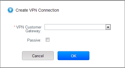
Select the desired customer gateway.
Select Passive if you want to establish a connection between two VPC
virtual routers.
If you want to establish a connection between two VPC virtual
routers, select Passive only on one of the VPC virtual routers, which
waits for the other VPC virtual router to initiate the connection. Do
not select Passive on the VPC virtual router that initiates the
connection.
Click OK to confirm.
Within a few moments, the VPN Connection is displayed.
The following information on the VPN connection is displayed:
- IP Address
- Gateway
- State
- IPSec Preshared Key
- IKE Policy
- ESP Policy
Site-to-Site VPN Connection Between VPC Networks
CloudStack provides you with the ability to establish a site-to-site VPN
connection between CloudStack virtual routers. To achieve that, add a
passive mode Site-to-Site VPN. With this functionality, users can deploy
applications in multiple Availability Zones or VPCs, which can
communicate with each other by using a secure Site-to-Site VPN Tunnel.
This feature is supported on all the hypervisors.
Create two VPCs. For example, VPC A and VPC B.
For more information, see “Configuring a Virtual Private Cloud”.
Create VPN gateways on both the VPCs you created.
For more information, see “Creating a VPN gateway
for the VPC”.
Create VPN customer gateway for both the VPCs.
For more information, see “Creating and Updating
a VPN Customer Gateway”.
Enable a VPN connection on VPC A in passive mode.
For more information, see “Creating a VPN
Connection”.
Ensure that the customer gateway is pointed to VPC B. The VPN
connection is shown in the Disconnected state.
Enable a VPN connection on VPC B.
Ensure that the customer gateway is pointed to VPC A. Because virtual
router of VPC A, in this case, is in passive mode and is waiting for
the virtual router of VPC B to initiate the connection, VPC B virtual
router should not be in passive mode.
The VPN connection is shown in the Disconnected state.
Creating VPN connection on both the VPCs initiates a VPN connection.
Wait for few seconds. The default is 30 seconds for both the VPN
connections to show the Connected state.
Restarting and Removing a VPN Connection
Log in to the CloudStack UI as an administrator or end user.
In the left navigation, choose Network.
In the Select view, select VPC.
All the VPCs that you have created for the account is listed in the
page.
Click the Configure button of the VPC to which you want to deploy the
VMs.
The VPC page is displayed where all the tiers you created are listed
in a diagram.
Click the Settings icon.
For each tier, the following options are displayed:
- Internal LB
- Public LB IP
- Static NAT
- Virtual Machines
- CIDR
The following router information is displayed:
- Private Gateways
- Public IP Addresses
- Site-to-Site VPNs
- Network ACL Lists
Select Site-to-Site VPN.
The Site-to-Site VPN page is displayed.
From the Select View drop-down, ensure that VPN Connection is
selected.
All the VPN connections you created are displayed.
Select the VPN connection you want to work with.
The Details tab is displayed.
To remove a VPN connection, click the Delete VPN connection button

To restart a VPN connection, click the Reset VPN connection button
present in the Details tab. 
About Inter-VLAN Routing (nTier Apps)
Inter-VLAN Routing (nTier Apps) is the capability to route network
traffic between VLANs. This feature enables you to build Virtual Private
Clouds (VPC), an isolated segment of your cloud, that can hold
multi-tier applications. These tiers are deployed on different VLANs
that can communicate with each other. You provision VLANs to the tiers
your create, and VMs can be deployed on different tiers. The VLANs are
connected to a virtual router, which facilitates communication between
the VMs. In effect, you can segment VMs by means of VLANs into different
networks that can host multi-tier applications, such as Web,
Application, or Database. Such segmentation by means of VLANs logically
separate application VMs for higher security and lower broadcasts, while
remaining physically connected to the same device.
This feature is supported on XenServer, KVM, and VMware hypervisors.
The major advantages are:
The administrator can deploy a set of VLANs and allow users to deploy
VMs on these VLANs. A guest VLAN is randomly alloted to an account
from a pre-specified set of guest VLANs. All the VMs of a certain
tier of an account reside on the guest VLAN allotted to that account.
Note
A VLAN allocated for an account cannot be shared between multiple accounts.
The administrator can allow users create their own VPC and deploy the
application. In this scenario, the VMs that belong to the account are
deployed on the VLANs allotted to that account.
Both administrators and users can create multiple VPCs. The guest
network NIC is plugged to the VPC virtual router when the first VM is
deployed in a tier.
The administrator can create the following gateways to send to or
receive traffic from the VMs:
- VPN Gateway: For more information, see “Creating a VPN gateway for the
VPC”.
- Public Gateway: The public gateway for a VPC is added to the
virtual router when the virtual router is created for VPC. The
public gateway is not exposed to the end users. You are not
allowed to list it, nor allowed to create any static routes.
- Private Gateway: For more information, see “Adding a Private Gateway to a VPC”.
Both administrators and users can create various possible
destinations-gateway combinations. However, only one gateway of each
type can be used in a deployment.
For example:
- VLANs and Public Gateway: For example, an application is
deployed in the cloud, and the Web application VMs communicate
with the Internet.
- VLANs, VPN Gateway, and Public Gateway: For example, an
application is deployed in the cloud; the Web application VMs
communicate with the Internet; and the database VMs communicate
with the on-premise devices.
The administrator can define Network Access Control List (ACL) on the
virtual router to filter the traffic among the VLANs or between the
Internet and a VLAN. You can define ACL based on CIDR, port range,
protocol, type code (if ICMP protocol is selected) and Ingress/Egress
type.
The following figure shows the possible deployment scenarios of a
Inter-VLAN setup:
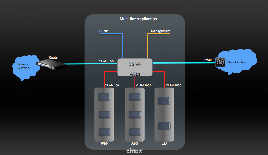
To set up a multi-tier Inter-VLAN deployment, see “Configuring a Virtual Private Cloud”.
Configuring a Virtual Private Cloud
About Virtual Private Clouds
CloudStack Virtual Private Cloud is a private, isolated part of
CloudStack. A VPC can have its own virtual network topology that
resembles a traditional physical network. You can launch VMs in the
virtual network that can have private addresses in the range of your
choice, for example: 10.0.0.0/16. You can define network tiers within
your VPC network range, which in turn enables you to group similar kinds
of instances based on IP address range.
For example, if a VPC has the private range 10.0.0.0/16, its guest
networks can have the network ranges 10.0.1.0/24, 10.0.2.0/24,
10.0.3.0/24, and so on.
Major Components of a VPC
A VPC is comprised of the following network components:
- VPC: A VPC acts as a container for multiple isolated networks
that can communicate with each other via its virtual router.
- Network Tiers: Each tier acts as an isolated network with its own
VLANs and CIDR list, where you can place groups of resources, such as
VMs. The tiers are segmented by means of VLANs. The NIC of each tier
acts as its gateway.
- Virtual Router: A virtual router is automatically created and
started when you create a VPC. The virtual router connect the tiers
and direct traffic among the public gateway, the VPN gateways, and
the NAT instances. For each tier, a corresponding NIC and IP exist in
the virtual router. The virtual router provides DNS and DHCP services
through its IP.
- Public Gateway: The traffic to and from the Internet routed to
the VPC through the public gateway. In a VPC, the public gateway is
not exposed to the end user; therefore, static routes are not support
for the public gateway.
- Private Gateway: All the traffic to and from a private network
routed to the VPC through the private gateway. For more information,
see “Adding a Private Gateway to a VPC”.
- VPN Gateway: The VPC side of a VPN connection.
- Site-to-Site VPN Connection: A hardware-based VPN connection
between your VPC and your datacenter, home network, or co-location
facility. For more information, see “Setting Up a Site-to-Site VPN Connection”.
- Customer Gateway: The customer side of a VPN Connection. For more
information, see “Creating and Updating a VPN
Customer Gateway”.
- NAT Instance: An instance that provides Port Address Translation
for instances to access the Internet via the public gateway. For more
information, see “Enabling or Disabling Static NAT on a VPC”.
- Network ACL: Network ACL is a group of Network ACL items. Network
ACL items are nothing but numbered rules that are evaluated in order,
starting with the lowest numbered rule. These rules determine whether
traffic is allowed in or out of any tier associated with the network
ACL. For more information, see “Configuring Network Access Control List”.
Network Architecture in a VPC
In a VPC, the following four basic options of network architectures are
present:
- VPC with a public gateway only
- VPC with public and private gateways
- VPC with public and private gateways and site-to-site VPN access
- VPC with a private gateway only and site-to-site VPN access
Connectivity Options for a VPC
You can connect your VPC to:
- The Internet through the public gateway.
- The corporate datacenter by using a site-to-site VPN connection
through the VPN gateway.
- Both the Internet and your corporate datacenter by using both the
public gateway and a VPN gateway.
VPC Network Considerations
Consider the following before you create a VPC:
- A VPC, by default, is created in the enabled state.
- A VPC can be created in Advance zone only, and can’t belong to more
than one zone at a time.
- The default number of VPCs an account can create is 20. However, you
can change it by using the max.account.vpcs global parameter, which
controls the maximum number of VPCs an account is allowed to create.
- The default number of tiers an account can create within a VPC is 3.
You can configure this number by using the vpc.max.networks
parameter.
- Each tier should have an unique CIDR in the VPC. Ensure that the
tier’s CIDR should be within the VPC CIDR range.
- A tier belongs to only one VPC.
- All network tiers inside the VPC should belong to the same account.
- When a VPC is created, by default, a SourceNAT IP is allocated to it.
The Source NAT IP is released only when the VPC is removed.
- A public IP can be used for only one purpose at a time. If the IP is
a sourceNAT, it cannot be used for StaticNAT or port forwarding.
- The instances can only have a private IP address that you provision.
To communicate with the Internet, enable NAT to an instance that you
launch in your VPC.
- Only new networks can be added to a VPC. The maximum number of
networks per VPC is limited by the value you specify in the
vpc.max.networks parameter. The default value is three.
- The load balancing service can be supported by only one tier inside
the VPC.
- If an IP address is assigned to a tier:
- That IP can’t be used by more than one tier at a time in the VPC.
For example, if you have tiers A and B, and a public IP1, you can
create a port forwarding rule by using the IP either for A or B,
but not for both.
- That IP can’t be used for StaticNAT, load balancing, or port
forwarding rules for another guest network inside the VPC.
- Remote access VPN is not supported in VPC networks.
Adding a Virtual Private Cloud
When creating the VPC, you simply provide the zone and a set of IP
addresses for the VPC network address space. You specify this set of
addresses in the form of a Classless Inter-Domain Routing (CIDR) block.
Log in to the CloudStack UI as an administrator or end user.
In the left navigation, choose Network.
In the Select view, select VPC.
Click Add VPC. The Add VPC page is displayed as follows:
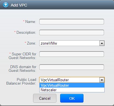
Provide the following information:
- Name: A short name for the VPC that you are creating.
- Description: A brief description of the VPC.
- Zone: Choose the zone where you want the VPC to be available.
- Super CIDR for Guest Networks: Defines the CIDR range for all
the tiers (guest networks) within a VPC. When you create a tier,
ensure that its CIDR is within the Super CIDR value you enter. The
CIDR must be RFC1918 compliant.
- DNS domain for Guest Networks: If you want to assign a special
domain name, specify the DNS suffix. This parameter is applied to
all the tiers within the VPC. That implies, all the tiers you
create in the VPC belong to the same DNS domain. If the parameter
is not specified, a DNS domain name is generated automatically.
- Public Load Balancer Provider: You have two options: VPC
Virtual Router and Netscaler.
Click OK.
Adding Tiers
Tiers are distinct locations within a VPC that act as isolated networks,
which do not have access to other tiers by default. Tiers are set up on
different VLANs that can communicate with each other by using a virtual
router. Tiers provide inexpensive, low latency network connectivity to
other tiers within the VPC.
Log in to the CloudStack UI as an administrator or end user.
In the left navigation, choose Network.
In the Select view, select VPC.
All the VPC that you have created for the account is listed in the
page.
Note
The end users can see their own VPCs, while root and domain admin can
see any VPC they are authorized to see.
Click the Configure button of the VPC for which you want to set up
tiers.
Click Create network.
The Add new tier dialog is displayed, as follows:
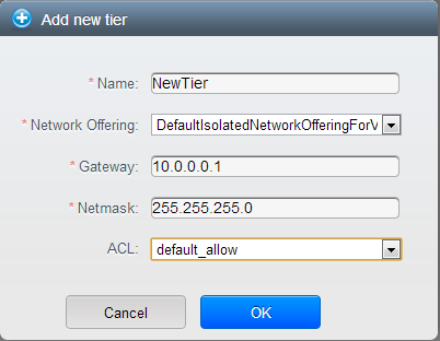
If you have already created tiers, the VPC diagram is displayed.
Click Create Tier to add a new tier.
Specify the following:
All the fields are mandatory.
Name: A unique name for the tier you create.
Network Offering: The following default network offerings are
listed: Internal LB,
DefaultIsolatedNetworkOfferingForVpcNetworksNoLB,
DefaultIsolatedNetworkOfferingForVpcNetworks
In a VPC, only one tier can be created by using LB-enabled network
offering.
Gateway: The gateway for the tier you create. Ensure that the
gateway is within the Super CIDR range that you specified while
creating the VPC, and is not overlapped with the CIDR of any
existing tier within the VPC.
VLAN: The VLAN ID for the tier that the root admin creates.
This option is only visible if the network offering you selected
is VLAN-enabled.
For more information, see “Assigning VLANs to
Isolated Networks”.
Netmask: The netmask for the tier you create.
For example, if the VPC CIDR is 10.0.0.0/16 and the network tier
CIDR is 10.0.1.0/24, the gateway of the tier is 10.0.1.1, and the
netmask of the tier is 255.255.255.0.
Click OK.
Continue with configuring access control list for the tier.
Configuring Network Access Control List
Define Network Access Control List (ACL) on the VPC virtual router to
control incoming (ingress) and outgoing (egress) traffic between the VPC
tiers, and the tiers and Internet. By default, all incoming traffic to
the guest networks is blocked and all outgoing traffic from guest
networks is allowed, once you add an ACL rule for outgoing traffic, then
only outgoing traffic specified in this ACL rule is allowed, the rest is
blocked. To open the ports, you must create a new network ACL. The
network ACLs can be created for the tiers only if the NetworkACL service
is supported.
About Network ACL Lists
In CloudStack terminology, Network ACL is a group of Network ACL items.
Network ACL items are nothing but numbered rules that are evaluated in
order, starting with the lowest numbered rule. These rules determine
whether traffic is allowed in or out of any tier associated with the
network ACL. You need to add the Network ACL items to the Network ACL,
then associate the Network ACL with a tier. Network ACL is associated
with a VPC and can be assigned to multiple VPC tiers within a VPC. A
Tier is associated with a Network ACL at all the times. Each tier can be
associated with only one ACL.
The default Network ACL is used when no ACL is associated. Default
behavior is all the incoming traffic is blocked and outgoing traffic is
allowed from the tiers. Default network ACL cannot be removed or
modified. Contents of the default Network ACL is:
| Rule |
Protocol |
Traffic type |
Action |
CIDR |
|---|
| 1 |
All |
Ingress |
Deny |
0.0.0.0/0 |
| 2 |
All |
Egress |
Deny |
0.0.0.0/0 |
Creating ACL Lists
Log in to the CloudStack UI as an administrator or end user.
In the left navigation, choose Network.
In the Select view, select VPC.
All the VPCs that you have created for the account is listed in the
page.
Click the Configure button of the VPC.
For each tier, the following options are displayed:
- Internal LB
- Public LB IP
- Static NAT
- Virtual Machines
- CIDR
The following router information is displayed:
- Private Gateways
- Public IP Addresses
- Site-to-Site VPNs
- Network ACL Lists
Select Network ACL Lists.
The following default rules are displayed in the Network ACLs page:
default_allow, default_deny.
Click Add ACL Lists, and specify the following:
- ACL List Name: A name for the ACL list.
- Description: A short description of the ACL list that can be
displayed to users.
Creating an ACL Rule
Log in to the CloudStack UI as an administrator or end user.
In the left navigation, choose Network.
In the Select view, select VPC.
All the VPCs that you have created for the account is listed in the
page.
Click the Configure button of the VPC.
Select Network ACL Lists.
In addition to the custom ACL lists you have created, the following
default rules are displayed in the Network ACLs page: default_allow,
default_deny.
Select the desired ACL list.
Select the ACL List Rules tab.
To add an ACL rule, fill in the following fields to specify what kind
of network traffic is allowed in the VPC.
- Rule Number: The order in which the rules are evaluated.
- CIDR: The CIDR acts as the Source CIDR for the Ingress rules,
and Destination CIDR for the Egress rules. To accept traffic only
from or to the IP addresses within a particular address block,
enter a CIDR or a comma-separated list of CIDRs. The CIDR is the
base IP address of the incoming traffic. For example,
192.168.0.0/22. To allow all CIDRs, set to 0.0.0.0/0.
- Action: What action to be taken. Allow traffic or block.
- Protocol: The networking protocol that sources use to send
traffic to the tier. The TCP and UDP protocols are typically used
for data exchange and end-user communications. The ICMP protocol
is typically used to send error messages or network monitoring
data. All supports all the traffic. Other option is Protocol
Number.
- Start Port, End Port (TCP, UDP only): A range of listening
ports that are the destination for the incoming traffic. If you
are opening a single port, use the same number in both fields.
- Protocol Number: The protocol number associated with IPv4 or
IPv6. For more information, see Protocol Numbers.
- ICMP Type, ICMP Code (ICMP only): The type of message and
error code that will be sent.
- Traffic Type: The type of traffic: Incoming or outgoing.
Click Add. The ACL rule is added.
You can edit the tags assigned to the ACL rules and delete the ACL
rules you have created. Click the appropriate button in the Details
tab.
Creating a Tier with Custom ACL List
Create a VPC.
Create a custom ACL list.
Add ACL rules to the ACL list.
Create a tier in the VPC.
Select the desired ACL list while creating a tier.
Click OK.
Assigning a Custom ACL List to a Tier
Create a VPC.
Create a tier in the VPC.
Associate the tier with the default ACL rule.
Create a custom ACL list.
Add ACL rules to the ACL list.
Select the tier for which you want to assign the custom ACL.
Click the Replace ACL List icon. 
The Replace ACL List dialog is displayed.
Select the desired ACL list.
Click OK.
Adding a Private Gateway to a VPC
A private gateway can be added by the root admin only. The VPC private
network has 1:1 relationship with the NIC of the physical network. You
can configure multiple private gateways to a single VPC. No gateways
with duplicated VLAN and IP are allowed in the same data center.
Log in to the CloudStack UI as an administrator or end user.
In the left navigation, choose Network.
In the Select view, select VPC.
All the VPCs that you have created for the account is listed in the
page.
Click the Configure button of the VPC to which you want to configure
load balancing rules.
The VPC page is displayed where all the tiers you created are listed
in a diagram.
Click the Settings icon.
The following options are displayed.
- Internal LB
- Public LB IP
- Static NAT
- Virtual Machines
- CIDR
The following router information is displayed:
- Private Gateways
- Public IP Addresses
- Site-to-Site VPNs
- Network ACL Lists
Select Private Gateways.
The Gateways page is displayed.
Click Add new gateway:
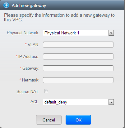
Specify the following:
Physical Network: The physical network you have created in the
zone.
IP Address: The IP address associated with the VPC gateway.
Gateway: The gateway through which the traffic is routed to
and from the VPC.
Netmask: The netmask associated with the VPC gateway.
VLAN: The VLAN associated with the VPC gateway.
Source NAT: Select this option to enable the source NAT
service on the VPC private gateway.
See “Source NAT on Private Gateway”.
ACL: Controls both ingress and egress traffic on a VPC private
gateway. By default, all the traffic is blocked.
See “ACL on Private Gateway”.
The new gateway appears in the list. You can repeat these steps to
add more gateway for this VPC.
Source NAT on Private Gateway
You might want to deploy multiple VPCs with the same super CIDR and
guest tier CIDR. Therefore, multiple guest VMs from different VPCs can
have the same IPs to reach a enterprise data center through the private
gateway. In such cases, a NAT service need to be configured on the
private gateway to avoid IP conflicts. If Source NAT is enabled, the
guest VMs in VPC reaches the enterprise network via private gateway IP
address by using the NAT service.
The Source NAT service on a private gateway can be enabled while adding
the private gateway. On deletion of a private gateway, source NAT rules
specific to the private gateway are deleted.
To enable source NAT on existing private gateways, delete them and
create afresh with source NAT.
ACL on Private Gateway
The traffic on the VPC private gateway is controlled by creating both
ingress and egress network ACL rules. The ACLs contains both allow and
deny rules. As per the rule, all the ingress traffic to the private
gateway interface and all the egress traffic out from the private
gateway interface are blocked.
You can change this default behaviour while creating a private gateway.
Alternatively, you can do the following:
In a VPC, identify the Private Gateway you want to work with.
In the Private Gateway page, do either of the following:
- Use the Quickview. See 3.
- Use the Details tab. See 4 through .
In the Quickview of the selected Private Gateway, click Replace ACL,
select the ACL rule, then click OK
Click the IP address of the Private Gateway you want to work with.
In the Detail tab, click the Replace ACL button.
The Replace ACL dialog is displayed.
select the ACL rule, then click OK.
Wait for few seconds. You can see that the new ACL rule is displayed
in the Details page.
Creating a Static Route
CloudStack enables you to specify routing for the VPN connection you
create. You can enter one or CIDR addresses to indicate which traffic is
to be routed back to the gateway.
In a VPC, identify the Private Gateway you want to work with.
In the Private Gateway page, click the IP address of the Private
Gateway you want to work with.
Select the Static Routes tab.
Specify the CIDR of destination network.
Click Add.
Wait for few seconds until the new route is created.
Blacklisting Routes
CloudStack enables you to block a list of routes so that they are not
assigned to any of the VPC private gateways. Specify the list of routes
that you want to blacklist in the blacklisted.routes global
parameter. Note that the parameter update affects only new static route
creations. If you block an existing static route, it remains intact and
continue functioning. You cannot add a static route if the route is
blacklisted for the zone.
Deploying VMs to the Tier
Log in to the CloudStack UI as an administrator or end user.
In the left navigation, choose Network.
In the Select view, select VPC.
All the VPCs that you have created for the account is listed in the
page.
Click the Configure button of the VPC to which you want to deploy the
VMs.
The VPC page is displayed where all the tiers you have created are
listed.
Click Virtual Machines tab of the tier to which you want to add a VM.
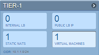
The Add Instance page is displayed.
Follow the on-screen instruction to add an instance. For information
on adding an instance, see the Installation Guide.
Deploying VMs to VPC Tier and Shared Networks
CloudStack allows you deploy VMs on a VPC tier and one or more shared
networks. With this feature, VMs deployed in a multi-tier application
can receive monitoring services via a shared network provided by a
service provider.
Log in to the CloudStack UI as an administrator.
In the left navigation, choose Instances.
Click Add Instance.
Select a zone.
Select a template or ISO, then follow the steps in the wizard.
Ensure that the hardware you have allows starting the selected
service offering.
Under Networks, select the desired networks for the VM you are
launching.
You can deploy a VM to a VPC tier and multiple shared networks.
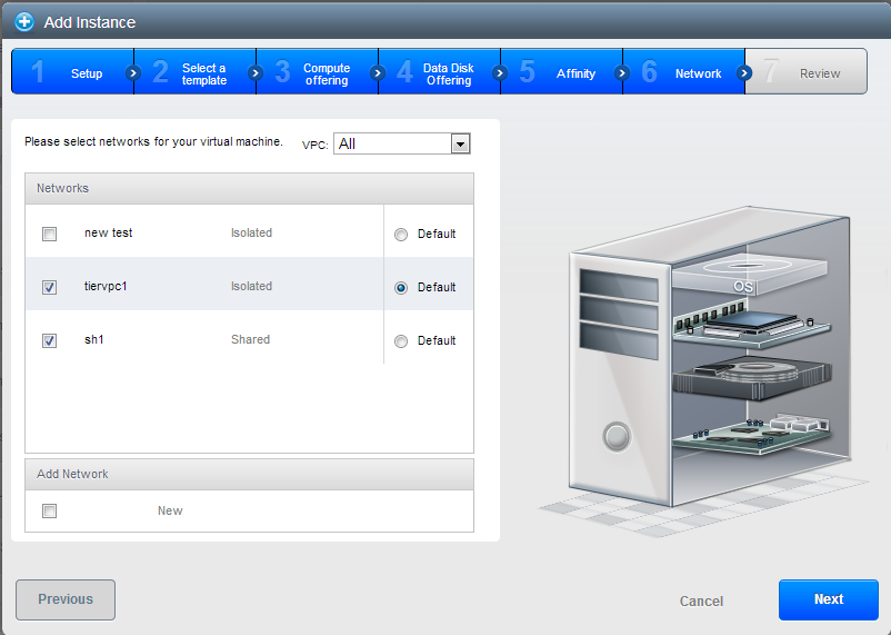
Click Next, review the configuration and click Launch.
Your VM will be deployed to the selected VPC tier and shared network.
Acquiring a New IP Address for a VPC
When you acquire an IP address, all IP addresses are allocated to VPC,
not to the guest networks within the VPC. The IPs are associated to the
guest network only when the first port-forwarding, load balancing, or
Static NAT rule is created for the IP or the network. IP can’t be
associated to more than one network at a time.
Log in to the CloudStack UI as an administrator or end user.
In the left navigation, choose Network.
In the Select view, select VPC.
All the VPCs that you have created for the account is listed in the
page.
Click the Configure button of the VPC to which you want to deploy the
VMs.
The VPC page is displayed where all the tiers you created are listed
in a diagram.
The following options are displayed.
- Internal LB
- Public LB IP
- Static NAT
- Virtual Machines
- CIDR
The following router information is displayed:
- Private Gateways
- Public IP Addresses
- Site-to-Site VPNs
- Network ACL Lists
Select IP Addresses.
The Public IP Addresses page is displayed.
Click Acquire New IP, and click Yes in the confirmation dialog.
You are prompted for confirmation because, typically, IP addresses
are a limited resource. Within a few moments, the new IP address
should appear with the state Allocated. You can now use the IP
address in port forwarding, load balancing, and static NAT rules.
Releasing an IP Address Alloted to a VPC
The IP address is a limited resource. If you no longer need a particular
IP, you can disassociate it from its VPC and return it to the pool of
available addresses. An IP address can be released from its tier, only
when all the networking ( port forwarding, load balancing, or StaticNAT
) rules are removed for this IP address. The released IP address will
still belongs to the same VPC.
Log in to the CloudStack UI as an administrator or end user.
In the left navigation, choose Network.
In the Select view, select VPC.
All the VPCs that you have created for the account is listed in the
page.
Click the Configure button of the VPC whose IP you want to release.
The VPC page is displayed where all the tiers you created are listed
in a diagram.
The following options are displayed.
- Internal LB
- Public LB IP
- Static NAT
- Virtual Machines
- CIDR
The following router information is displayed:
- Private Gateways
- Public IP Addresses
- Site-to-Site VPNs
- Network ACL Lists
Select Public IP Addresses.
The IP Addresses page is displayed.
Click the IP you want to release.
In the Details tab, click the Release IP button
Enabling or Disabling Static NAT on a VPC
A static NAT rule maps a public IP address to the private IP address of
a VM in a VPC to allow Internet traffic to it. This section tells how to
enable or disable static NAT for a particular IP address in a VPC.
If port forwarding rules are already in effect for an IP address, you
cannot enable static NAT to that IP.
If a guest VM is part of more than one network, static NAT rules will
function only if they are defined on the default network.
Log in to the CloudStack UI as an administrator or end user.
In the left navigation, choose Network.
In the Select view, select VPC.
All the VPCs that you have created for the account is listed in the
page.
Click the Configure button of the VPC to which you want to deploy the
VMs.
The VPC page is displayed where all the tiers you created are listed
in a diagram.
For each tier, the following options are displayed.
- Internal LB
- Public LB IP
- Static NAT
- Virtual Machines
- CIDR
The following router information is displayed:
- Private Gateways
- Public IP Addresses
- Site-to-Site VPNs
- Network ACL Lists
In the Router node, select Public IP Addresses.
The IP Addresses page is displayed.
Click the IP you want to work with.
In the Details tab,click the Static NAT button.
The button toggles between Enable and
Disable, depending on whether static NAT is currently enabled for the
IP address.
If you are enabling static NAT, a dialog appears as follows:
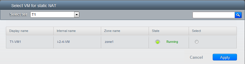
Select the tier and the destination VM, then click Apply.
Adding Load Balancing Rules on a VPC
In a VPC, you can configure two types of load balancing: external LB and
internal LB. External LB is nothing but a LB rule created to redirect
the traffic received at a public IP of the VPC virtual router. The
traffic is load balanced within a tier based on your configuration.
Citrix NetScaler and VPC virtual router are supported for external LB.
When you use internal LB service, traffic received at a tier is load
balanced across different VMs within that tier. For example, traffic
reached at Web tier is redirected to another VM in that tier. External
load balancing devices are not supported for internal LB. The service is
provided by a internal LB VM configured on the target tier.
Load Balancing Within a Tier (External LB)
A CloudStack user or administrator may create load balancing rules that
balance traffic received at a public IP to one or more VMs that belong
to a network tier that provides load balancing service in a VPC. A user
creates a rule, specifies an algorithm, and assigns the rule to a set of
VMs within a tier.
Creating a Network Offering for External LB
To have external LB support on VPC, create a network offering as
follows:
- Log in to the CloudStack UI as a user or admin.
- From the Select Offering drop-down, choose Network Offering.
- Click Add Network Offering.
- In the dialog, make the following choices:
- Name: Any desired name for the network offering.
- Description: A short description of the offering that can be
displayed to users.
- Network Rate: Allowed data transfer rate in MB per second.
- Traffic Type: The type of network traffic that will be carried
on the network.
- Guest Type: Choose whether the guest network is isolated or
shared.
- Persistent: Indicate whether the guest network is persistent
or not. The network that you can provision without having to
deploy a VM on it is termed persistent network.
- VPC: This option indicate whether the guest network is Virtual
Private Cloud-enabled. A Virtual Private Cloud (VPC) is a private,
isolated part of CloudStack. A VPC can have its own virtual
network topology that resembles a traditional physical network.
For more information on VPCs, see “About Virtual Private Clouds”.
- Specify VLAN: (Isolated guest networks only) Indicate whether
a VLAN should be specified when this offering is used.
- Supported Services: Select Load Balancer. Use Netscaler or
VpcVirtualRouter.
- Load Balancer Type: Select Public LB from the drop-down.
- LB Isolation: Select Dedicated if Netscaler is used as the
external LB provider.
- System Offering: Choose the system service offering that you
want virtual routers to use in this network.
- Conserve mode: Indicate whether to use conserve mode. In this
mode, network resources are allocated only when the first virtual
machine starts in the network.
- Click OK and the network offering is created.
Creating an External LB Rule
Log in to the CloudStack UI as an administrator or end user.
In the left navigation, choose Network.
In the Select view, select VPC.
All the VPCs that you have created for the account is listed in the
page.
Click the Configure button of the VPC, for which you want to
configure load balancing rules.
The VPC page is displayed where all the tiers you created listed in a
diagram.
For each tier, the following options are displayed:
- Internal LB
- Public LB IP
- Static NAT
- Virtual Machines
- CIDR
The following router information is displayed:
- Private Gateways
- Public IP Addresses
- Site-to-Site VPNs
- Network ACL Lists
In the Router node, select Public IP Addresses.
The IP Addresses page is displayed.
Click the IP address for which you want to create the rule, then
click the Configuration tab.
In the Load Balancing node of the diagram, click View All.
Select the tier to which you want to apply the rule.
Specify the following:
- Name: A name for the load balancer rule.
- Public Port: The port that receives the incoming traffic to be
balanced.
- Private Port: The port that the VMs will use to receive the
traffic.
- Algorithm. Choose the load balancing algorithm you want
CloudStack to use. CloudStack supports the following well-known
algorithms:
- Round-robin
- Least connections
- Source
- Stickiness. (Optional) Click Configure and choose the
algorithm for the stickiness policy. See Sticky Session Policies
for Load Balancer Rules.
- Add VMs: Click Add VMs, then select two or more VMs that will
divide the load of incoming traffic, and click Apply.
The new load balancing rule appears in the list. You can repeat these
steps to add more load balancing rules for this IP address.
Load Balancing Across Tiers
CloudStack supports sharing workload across different tiers within your
VPC. Assume that multiple tiers are set up in your environment, such as
Web tier and Application tier. Traffic to each tier is balanced on the
VPC virtual router on the public side, as explained in
“Adding Load Balancing Rules on a VPC”.
If you want the traffic coming
from the Web tier to the Application tier to be balanced, use the
internal load balancing feature offered by CloudStack.
How Does Internal LB Work in VPC?
In this figure, a public LB rule is created for the public IP
72.52.125.10 with public port 80 and private port 81. The LB rule,
created on the VPC virtual router, is applied on the traffic coming from
the Internet to the VMs on the Web tier. On the Application tier two
internal load balancing rules are created. An internal LB rule for the
guest IP 10.10.10.4 with load balancer port 23 and instance port 25 is
configured on the VM, InternalLBVM1. Another internal LB rule for the
guest IP 10.10.10.4 with load balancer port 45 and instance port 46 is
configured on the VM, InternalLBVM1. Another internal LB rule for the
guest IP 10.10.10.6, with load balancer port 23 and instance port 25 is
configured on the VM, InternalLBVM2.
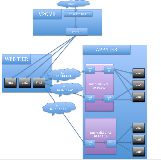
Guidelines
- Internal LB and Public LB are mutually exclusive on a tier. If the
tier has LB on the public side, then it can’t have the Internal LB.
- Internal LB is supported just on VPC networks in CloudStack 4.2
release.
- Only Internal LB VM can act as the Internal LB provider in CloudStack
4.2 release.
- Network upgrade is not supported from the network offering with
Internal LB to the network offering with Public LB.
- Multiple tiers can have internal LB support in a VPC.
- Only one tier can have Public LB support in a VPC.
Creating a Network Offering for Internal LB
To have internal LB support on VPC, either use the default offering,
DefaultIsolatedNetworkOfferingForVpcNetworksWithInternalLB, or create a
network offering as follows:
- Log in to the CloudStack UI as a user or admin.
- From the Select Offering drop-down, choose Network Offering.
- Click Add Network Offering.
- In the dialog, make the following choices:
- Name: Any desired name for the network offering.
- Description: A short description of the offering that can be
displayed to users.
- Network Rate: Allowed data transfer rate in MB per second.
- Traffic Type: The type of network traffic that will be carried
on the network.
- Guest Type: Choose whether the guest network is isolated or
shared.
- Persistent: Indicate whether the guest network is persistent
or not. The network that you can provision without having to
deploy a VM on it is termed persistent network.
- VPC: This option indicate whether the guest network is Virtual
Private Cloud-enabled. A Virtual Private Cloud (VPC) is a private,
isolated part of CloudStack. A VPC can have its own virtual
network topology that resembles a traditional physical network.
For more information on VPCs, see “About Virtual
Private Clouds”.
- Specify VLAN: (Isolated guest networks only) Indicate whether
a VLAN should be specified when this offering is used.
- Supported Services: Select Load Balancer. Select
InternalLbVM from the provider list.
- Load Balancer Type: Select Internal LB from the drop-down.
- System Offering: Choose the system service offering that you
want virtual routers to use in this network.
- Conserve mode: Indicate whether to use conserve mode. In this
mode, network resources are allocated only when the first virtual
machine starts in the network.
- Click OK and the network offering is created.
Creating an Internal LB Rule
When you create the Internal LB rule and applies to a VM, an Internal LB
VM, which is responsible for load balancing, is created.
You can view the created Internal LB VM in the Instances page if you
navigate to Infrastructure > Zones > <zone_ name> >
<physical_network_name> > Network Service Providers > Internal
LB VM. You can manage the Internal LB VMs as and when required from
the location.
Log in to the CloudStack UI as an administrator or end user.
In the left navigation, choose Network.
In the Select view, select VPC.
All the VPCs that you have created for the account is listed in the
page.
Locate the VPC for which you want to configure internal LB, then
click Configure.
The VPC page is displayed where all the tiers you created listed in a
diagram.
Locate the Tier for which you want to configure an internal LB rule,
click Internal LB.
In the Internal LB page, click Add Internal LB.
In the dialog, specify the following:
Name: A name for the load balancer rule.
Description: A short description of the rule that can be
displayed to users.
Source IP Address: (Optional) The source IP from which traffic
originates. The IP is acquired from the CIDR of that particular
tier on which you want to create the Internal LB rule. If not
specified, the IP address is automatically allocated from the
network CIDR.
For every Source IP, a new Internal LB VM is created for load
balancing.
Source Port: The port associated with the source IP. Traffic
on this port is load balanced.
Instance Port: The port of the internal LB VM.
Algorithm. Choose the load balancing algorithm you want
CloudStack to use. CloudStack supports the following well-known
algorithms:
- Round-robin
- Least connections
- Source
Adding a Port Forwarding Rule on a VPC
Log in to the CloudStack UI as an administrator or end user.
In the left navigation, choose Network.
In the Select view, select VPC.
All the VPCs that you have created for the account is listed in the
page.
Click the Configure button of the VPC to which you want to deploy the
VMs.
The VPC page is displayed where all the tiers you created are listed
in a diagram.
For each tier, the following options are displayed:
- Internal LB
- Public LB IP
- Static NAT
- Virtual Machines
- CIDR
The following router information is displayed:
- Private Gateways
- Public IP Addresses
- Site-to-Site VPNs
- Network ACL Lists
In the Router node, select Public IP Addresses.
The IP Addresses page is displayed.
Click the IP address for which you want to create the rule, then
click the Configuration tab.
In the Port Forwarding node of the diagram, click View All.
Select the tier to which you want to apply the rule.
Specify the following:
Public Port: The port to which public traffic will be
addressed on the IP address you acquired in the previous step.
Private Port: The port on which the instance is listening for
forwarded public traffic.
Protocol: The communication protocol in use between the two
ports.
Add VM: Click Add VM. Select the name of the instance to which
this rule applies, and click Apply.
You can test the rule by opening an SSH session to the instance.
Removing Tiers
You can remove a tier from a VPC. A removed tier cannot be revoked. When
a tier is removed, only the resources of the tier are expunged. All the
network rules (port forwarding, load balancing and staticNAT) and the IP
addresses associated to the tier are removed. The IP address still be
belonging to the same VPC.
Log in to the CloudStack UI as an administrator or end user.
In the left navigation, choose Network.
In the Select view, select VPC.
All the VPC that you have created for the account is listed in the
page.
Click the Configure button of the VPC for which you want to set up
tiers.
The Configure VPC page is displayed. Locate the tier you want to work
with.
Select the tier you want to remove.
In the Network Details tab, click the Delete Network button.

Click Yes to confirm. Wait for some time for the tier to be removed.
Editing, Restarting, and Removing a Virtual Private Cloud
Note
Ensure that all the tiers are removed before you remove a VPC.
Log in to the CloudStack UI as an administrator or end user.
In the left navigation, choose Network.
In the Select view, select VPC.
All the VPCs that you have created for the account is listed in the
page.
Select the VPC you want to work with.
In the Details tab, click the Remove VPC button 
You can remove the VPC by also using the remove button in the Quick
View.
You can edit the name and description of a VPC. To do that, select
the VPC, then click the Edit button.
To restart a VPC, select the VPC, then click the Restart button.

Persistent Networks
The network that you can provision without having to deploy any VMs on
it is called a persistent network. A persistent network can be part of a
VPC or a non-VPC environment.
When you create other types of network, a network is only a database
entry until the first VM is created on that network. When the first VM
is created, a VLAN ID is assigned and the network is provisioned. Also,
when the last VM is destroyed, the VLAN ID is released and the network
is no longer available. With the addition of persistent network, you
will have the ability to create a network in CloudStack in which
physical devices can be deployed without having to run any VMs.
Additionally, you can deploy physical devices on that network.
One of the advantages of having a persistent network is that you can
create a VPC with a tier consisting of only physical devices. For
example, you might create a VPC for a three-tier application, deploy VMs
for Web and Application tier, and use physical machines for the Database
tier. Another use case is that if you are providing services by using
physical hardware, you can define the network as persistent and
therefore even if all its VMs are destroyed the services will not be
discontinued.
Persistent Network Considerations
- Persistent network is designed for isolated networks.
- All default network offerings are non-persistent.
- A network offering cannot be editable because changing it affects the
behavior of the existing networks that were created using this
network offering.
- When you create a guest network, the network offering that you select
defines the network persistence. This in turn depends on whether
persistent network is enabled in the selected network offering.
- An existing network can be made persistent by changing its network
offering to an offering that has the Persistent option enabled. While
setting this property, even if the network has no running VMs, the
network is provisioned.
- An existing network can be made non-persistent by changing its
network offering to an offering that has the Persistent option
disabled. If the network has no running VMs, during the next network
garbage collection run the network is shut down.
- When the last VM on a network is destroyed, the network garbage
collector checks if the network offering associated with the network
is persistent, and shuts down the network only if it is
non-persistent.
Creating a Persistent Guest Network
To create a persistent network, perform the following:
Create a network offering with the Persistent option enabled.
See “Creating a New Network Offering”.
Select Network from the left navigation pane.
Select the guest network that you want to offer this network service
to.
Click the Edit button.
From the Network Offering drop-down, select the persistent network
offering you have just created.
Click OK.
Setup a Palo Alto Networks Firewall
Functionality Provided
This implementation enables the orchestration of a Palo Alto Networks Firewall
from within CloudStack UI and API.
The following features are supported:
- List/Add/Delete Palo Alto Networks service provider
- List/Add/Delete Palo Alto Networks network service offering
- List/Add/Delete Palo Alto Networks network using the above service offering
- Add an instance to a Palo Alto Networks network
- Source NAT management on network create and delete
- List/Add/Delete Ingress Firewall rule
- List/Add/Delete Egress Firewall rule (both ‘Allow’ and ‘Deny’ default rules
supported)
- List/Add/Delete Port Forwarding rule
- List/Add/Delete Static NAT rule
- Apply a Threat Profile to all firewall rules (more details in the
Additional Features section)
- Apply a Log Forwarding profile to all firewall rules (more details in the
Additional Features section)
Initial Palo Alto Networks Firewall Configuration
Anatomy of the Palo Alto Networks Firewall
- In ‘Network > Interfaces’ there is a list of physical interfaces as
well as aggregated physical interfaces which are used for managing traffic
in and out of the Palo Alto Networks Firewall device.
- In ‘Network > Zones’ there is a list of the different configuration
zones. This implementation will use two zones; a public (defaults to
‘untrust’) and private (defaults to ‘trust’) zone.
- In ‘Network > Virtual Routers’ there is a list of VRs which handle
traffic routing for the Palo Alto Firewall. We only use a single Virtual
Router on the firewall and it is used to handle all the routing to the next
network hop.
- In ‘Objects > Security Profile Groups’ there is a list of profiles
which can be applied to firewall rules. These profiles are used to better
understand the types of traffic that is flowing through your network.
Configured when you add the firewall provider to CloudStack.
- In ‘Objects > Log Forwarding’ there is a list of profiles which can be
applied to firewall rules. These profiles are used to better track the
logs generated by the firewall. Configured when you add the firewall
provider to CloudStack.
- In ‘Policies > Security’ there is a list of firewall rules that are
currently configured. You will not need to modify this section because it
will be completely automated by CloudStack, but you can review the firewall
rules which have been created here.
- In ‘Policies > NAT’ there is a list of the different NAT rules. You
will not need to modify this section because it will be completely
automated by CloudStack, but you can review the different NAT rules that
have been created here. Source NAT, Static NAT and Destination NAT (Port
Forwarding) rules will show up in this list.
Commit configuration on the Palo Alto Networks Firewall
In order for all the changes we just made to take effect, we need to commit
the changes.
- Click the ‘Commit’ link in the top right corner of the window
- Click ‘OK’ in the commit window overlay
- Click ‘Close’ to the resulting commit status window after the commit
finishes
Setup the Palo Alto Networks Firewall in CloudStack
Add the Palo Alto Networks Firewall as a Service Provider
- Navigate to ‘Infrastructure > Zones > ZONE_NAME > Physical Network >
NETWORK_NAME (guest) > Configure; Network Service Providers’
- Click on ‘Palo Alto’ in the list
- Click ‘View Devices’
- Click ‘Add Palo Alto Device’
- Enter your configuration in the overlay. This example will reflect the
details previously used in this guide.
- IP Address: (the IP of the Palo Alto Networks Firewall)
- Username: (the admin username for the firewall)
- Password: (the admin password for the firewall)
- Type: Palo Alto Firewall
- Public Interface: ethernet1/1 (use what you setup earlier as the
public interface if it is different from my examples)
- Private Interface: ethernet1/2 (use what you setup earlier as the
private interface if it is different from my examples)
- Number of Retries: 2 (the default is fine)
- Timeout: 300 (the default is fine)
- Public Network: untrust (this is the public zone on the firewall and
did not need to be configured)
- Private Network: trust (this is the private zone on the firewall and
did not need to be configured)
- Virtual Router: default (this is the name of the Virtual Router we
setup on the firewall)
- Palo Alto Threat Profile: (not required. name of the ‘Security
Profile Groups’ to apply. more details in the ‘Additional Features’
section)
- Palo Alto Log Profile: (not required. name of the ‘Log Forwarding’
profile to apply. more details in the ‘Additional Features’ section)
- Capacity: (not required)
- Dedicated: (not required)
- Click ‘OK’
- Click on ‘Palo Alto’ in the breadcrumbs to go back one screen.
- Click on ‘Enable Provider’
Add a Network Service Offering to use the new Provider
There are 6 ‘Supported Services’ that need to be configured in the network
service offering for this functionality. They are DHCP, DNS, Firewall, Source
NAT, Static NAT and Port Forwarding. For the other settings, there are
probably additional configurations which will work, but I will just document a
common case.
- Navigate to ‘Service Offerings’
- In the drop-down at the top, select ‘Network Offerings’
- Click ‘Add Network Offering’
- Name: (name it whatever you want)
- Description: (again, can be whatever you want)
- Guest Type: Isolated
- Supported Services:
- DHCP: Provided by ‘VirtualRouter’
- DNS: Provided by ‘VirtualRouter’
- Firewall: Provided by ‘PaloAlto’
- Source NAT: Provided by ‘PaloAlto’
- Static NAT: Provided by ‘PaloAlto’
- Port Forwarding: Provided by ‘PaloAlto’
- System Offering for Router: System Offering For Software Router
- Supported Source NAT Type: Per account (this is the only supported
option)
- Default egress policy: (both ‘Allow’ and ‘Deny’ are supported)
- Click ‘OK’
- Click on the newly created service offering
- Click ‘Enable network offering’
When adding networks in CloudStack, select this network offering to use the
Palo Alto Networks firewall.
Additional Features
In addition to the standard functionality exposed by CloudStack, we have added
a couple additional features to this implementation. We did not add any new
screens to CloudStack, but we have added a couple fields to the ‘Add Palo Alto
Service Provider’ screen which will add functionality globally for the device.
Palo Alto Networks Threat Profile
This feature allows you to specify a ‘Security Profile Group’ to be applied to
all of the firewall rules which are created on the Palo Alto Networks firewall
device.
To create a ‘Security Profile Group’ on the Palo Alto Networks firewall, do
the following:
- Log into the Palo Alto Networks firewall
- Navigate to ‘Objects > Security Profile Groups’
- Click ‘Add’ at the bottom of the page to add a new group
- Give the group a Name and specify the profiles you would like to include in
the group
- Click ‘OK’
- Click the ‘Commit’ link in the top right of the screen and follow the on
screen instructions
Once you have created a profile, you can reference it by Name in the ‘Palo
Alto Threat Profile’ field in the ‘Add the Palo Alto Networks Firewall as a
Service Provider’ step.
Palo Alto Networks Log Forwarding Profile
This feature allows you to specify a ‘Log Forwarding’ profile to better manage
where the firewall logs are sent to. This is helpful for keeping track of
issues that can arise on the firewall.
To create a ‘Log Forwarding’ profile on the Palo Alto Networks Firewall, do
the following:
- Log into the Palo Alto Networks firewall
- Navigate to ‘Objects > Log Forwarding’
- Click ‘Add’ at the bottom of the page to add a new profile
- Give the profile a Name and specify the details you want for the traffic
and threat settings
- Click ‘OK’
- Click the ‘Commit’ link in the top right of the screen and follow the on
screen instructions
Once you have created a profile, you can reference it by Name in the ‘Palo
Alto Log Profile’ field in the ‘Add the Palo Alto Networks Firewall as a
Service Provider’ step.
Limitations
- The implementation currently only supports a single public IP range in
CloudStack
- Usage tracking is not yet implemented